If it has a phase shift cap, it is an AC sync motor and it will depend on the power requirement. Papst also made AC induction motors that were quite high power, but this would appear to be a sync motor.
The Falcon is limited to 5W max, the Eagle will drive motors up to 15W. You would plug the motor's wall adapter into the PSU output. The Falcon is also 115VAC output only. You would need a step up xfmr or a different wall adapter if it is designed for 220VAC. The Eagle is jumper selectable for 115/230VAC output.
Both the Falcon and Eagle have universal input (100-260VAC) power supplies. Both are front panel programmable for 50/60Hz pulley operation.
Thanks for the reply. It's definitely an ac sync motor. I've no idea of its wattage but I suspect it's low.
Looks like i am 300rpm, 7.5W, so please add me to your list for new when the Eagle is available. Thanks.
Receeved today. 2 Days UPS from Wisconsin to NJ....pretty impressive UPS!
So...
Close....
But keep me on that Eagle list
Attachments
I have a Lenco with a 60hz motor and would be interested in purchasing your controller. Please contact me when you have units available for sale.
Thanks
I'm not able to PM you (you must have that disabled?).
We will start shipping the Eagle PSU on Monday Dec 22nd. The hardware is complete, assembled and tested and the only thing we are waiting for is the packing foam which will arrive on Monday.
You can contact me directly at: bill@phoenix-engr.com
Just received my new Eagle power supply, just in time for Christmas. Thanks Phoenix for getting it out on time.
This thing is remarkably small, the controller fits easily under the table. The amp is a little bigger, but with the 6ft cable, it fits comfortably behind the stand. Runs like a champ! I also got the Roadrunner tach and is this set up ever sweet. The speed started off fairly close to begin with, but within 3-4 revs was spot on and never drifted more than .003-4 RPM while listening for hours. Brilliant piece of engineering. Head and shoulders above the SDS.
This thing is remarkably small, the controller fits easily under the table. The amp is a little bigger, but with the 6ft cable, it fits comfortably behind the stand. Runs like a champ! I also got the Roadrunner tach and is this set up ever sweet. The speed started off fairly close to begin with, but within 3-4 revs was spot on and never drifted more than .003-4 RPM while listening for hours. Brilliant piece of engineering. Head and shoulders above the SDS.
Looks like my turntable motor is a power *****. I plugged an ammeter between the power cord and the wall and discovered my DIY turntable with the 3-phase Papst motor pulls 0.19A from the 119.6VAC coming out of my wall. So I'd need at least a 25W amplifier, which I believe means I cannot use the Eagle either for this table.
So bummed! I was planning to buy one after Christmas. Still may get the Roadrunner, but I already know that the table runs fast, so I need an adjustable frequency solution. Guess I'll be out looking for a used VPI SDS. That still doesn't give me the autocorrecting speed feedback.
Sigh.
So bummed! I was planning to buy one after Christmas. Still may get the Roadrunner, but I already know that the table runs fast, so I need an adjustable frequency solution. Guess I'll be out looking for a used VPI SDS. That still doesn't give me the autocorrecting speed feedback.
Sigh.
Pyramid,
I have a 49mm 24v Hurst motor that's around 3-6w. Currently using an offset 60Hz sine off MP3 and amp to drive the motor. Could a 24v toroid be used to power the motor, and the Falcon to driver the 115v of the power toroid?
My_TT_11 - My Photo Gallery
Thanks,
Vince
I have a 49mm 24v Hurst motor that's around 3-6w. Currently using an offset 60Hz sine off MP3 and amp to drive the motor. Could a 24v toroid be used to power the motor, and the Falcon to driver the 115v of the power toroid?
My_TT_11 - My Photo Gallery
Thanks,
Vince
Nice Table!
It shouldn't be a problem to run a 3W motor through a 115->24V transformer. The xfmr losses should be minimal (as long as you use an appropriately sized xfmr). 6W might be pushing it, again depending upon the losses involved.
If you are running from a split phase supply now, you of course will need to add the phase shift cap back into the mix (but you probably know that if you doing this kind of work).
The RoadRunner tach will produce an accurate reading within 2 revs. If connected to the PSU, the PSU will start correcting the speed (if needed) after 4 revs. If you want to see how far off it is or how much it drifts with time, don't connect the cable between the tach and PSU. You can manually adjust the speed on the PSU and measure it with the tach. When connected together, this happens automatically.
Hurst motor 3001-003 is listed as 3w. http://www.hurst-motors.com/aabdirectdrive.html
Should it be a low or high VA? I imagine the motor doesn't require much current.
Thanks
Vince
as long as you use an appropriately sized xfmr
Should it be a low or high VA? I imagine the motor doesn't require much current.
Thanks
Vince
Last edited:
Just got notification that the Phoenix Falcon I ordered yesterday has been shipped! I'll be using it to power my VPI Scout, which should work fine.
What I really wanted to do was to buy a Phoenix Eagle for my big DIY table. Unfortunately, the motor I've used in that is a power hog and at 23watts is too great a load for the Eagle. So, my plan is to build a power supply box that contains a phase-splitting network to take the Falcon controller output and generate three sine waves 120 degrees apart, as well as three amplifiers to boost that signal to drive each of the sets of windings in the Papst.
I'm hoping to use an inexpensive lm3886 chip-amp for each of the three amps. But I'm uncertain about how to deal with the output. I previously experimented with some cheap chip amps and promptly burned them up. I was connecting them to the motor via step-up transformers. The combined inductance/load of the transformer plus motor was not a happy surprise for the chip amps!
Any tips on how the Eagle is able to generate the voltage & current for up to 15 watt devices? I have a lot of reading to do before I build my next generation of amps.
Thx!
Whenever you drive reactive loads, you will want to provide transient voltage suppression (TVS) diodes on the output that will clamp it to the supply rails (reverse bias the diodes). These should be able to handle high voltages and currents with fast switching times.
To prevent the possibility of oscillations, an RC Zoebel network on the output is also advised (3.9 Ohms to ground through 4.7uFd cap.
Make sure the amp and xfmr has sufficient capacity headroom for the task (at least 50% overrated is a good starting point).
To prevent the possibility of oscillations, an RC Zoebel network on the output is also advised (3.9 Ohms to ground through 4.7uFd cap.
Make sure the amp and xfmr has sufficient capacity headroom for the task (at least 50% overrated is a good starting point).
")
Eagle PSU vs VPI SDS
Finally got my hands on a VPI SDS to do some tests. Interesting circuit; who ever designed this thing at K-Tron Electronics did a couple of clever things I hadn't seen before. I know it was designed in the late 90's and DDS was more expensive back then, but I'm really surprised they decided to go the PLL route; it really added to the complexity of the circuit (and manufacturing costs) as well as negatively affecting the performance.
The output frequency step is 0.01 Hz; with a PLL circuit this would normally mean extremely long lock times and lots of wobble. K-Tron got around this by scaling everything by 2^16 times. The frequency step then becomes 655.36 Hz with a loop natural frequency of a couple hundred Hz. This still has a considerable lock time, which is why the output frequency has to move 1Hz at a time when switching between 33 and 45 RPM. If they tried to move in one step, the loop may loose lock altogether or the overshoot would do horrible things to the output and the motor. Even changing 1Hz at a time, you can see quite a bit of wobble in the output. Compare this to DDS which has settling times in the microsecond range.
The way the whole SDS scheme functions is built around U5, a CS82C54 triple 16bit programmable counter timer:
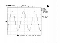
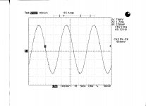
The µP xtal frequency is 7.3728MHz; counter 0 of U5 divides this by a fixed number (11,250) to produce the 655.36Hz reference for the PLL. The MC4046 PLL VCO operates at 2^16 times the output frequency (60-81Hz) which is 3.93216-5.308416 MHz. This is divided in counter 1 of U5, by 6000-8100 to produce the other 655.36 Hz signal for the 4046 phase detector. The output of the VCO is also divided in counter 2 by a fixed number (4096) to produce output freq x 16 (960Hz-1296Hz). This Fo x16 signal drives U7, an MC4024 binary counter; the lower 4 output bits are used as address bits for U8, an MC4067 16:1 analog mux with different resistor values on each of the 16 inputs and acts as a simple D to A converter. The stepped sine wave is 1/16th the input clock frequency of U7, or 60-81Hz. The stepped waveform output of U8 only has 8 levels, so it is essentially a 3 bit DAC clocked at 16x the output frequency (see SDS DAC Out.jpg). Compare this to the DDS output of the Eagle which uses a 10bit DAC and a clock frequency 150x higher than the output signal (Eagle DDS Out.jpg).
The SDS signal is then LPF by a 2 pole Sallen Key filter with a Fc of 191Hz and a 12dB/octave rolloff. The filter removes most of the staircase steps, but does little to nothing about harmonic content. This can be seen in the spectrum display (SDS Harmonics.jpg) where the 3rd harmonic is much higher than in the Eagle output. The distortion of the un-amplified signal is actually quite good at ~0.2% THD, given only one stage of filtering. The Eagle distortion level is ~14dB better at 0.04%.
Voltage adjustment is done by another 8:1 analog mux (U11 MC14051) that switches in 8 resistors that form an 8 step voltage divider.
The filtered output feeds an LM392 opamp which drives a complimentary output arrangement of 2N3904/2N3906 bipolars driving the MOSFET output transistors (P2955/IRF530). The output is AC coupled to a 6.3V-120V IE construction iron core transformer rated at 20W. The output voltage sagged quite a bit from 113.1VAC no load to 109.5VAC at 4W, 106VAC at 8W, 102VAC at 12W, 98.7VAC at 16W and 95.2VAC at 20W. The heat sinks on the output transistors are way too small to run the SDS at much more than 12W for any length of time. The SDS has a very heavy steel case; not sure why you wouldn't take advantage of this and put an external heat sink on the back and mount the transistors to the case.
The SDS performed reasonably well given it is a 15+ year old design. It could definitely benefit from a redesign using newer technology; it's not hard to see why it costs $1200. The frequency generating section comprised of 6 ICs and ~50 Rs & Cs could be replaced by a single DDS chip. The 8 step attenuator and a dozen components could be replaced by a 32 step digital pot in a single SOT6 package. But then you would essentially have the Eagle.
Finally got my hands on a VPI SDS to do some tests. Interesting circuit; who ever designed this thing at K-Tron Electronics did a couple of clever things I hadn't seen before. I know it was designed in the late 90's and DDS was more expensive back then, but I'm really surprised they decided to go the PLL route; it really added to the complexity of the circuit (and manufacturing costs) as well as negatively affecting the performance.
The output frequency step is 0.01 Hz; with a PLL circuit this would normally mean extremely long lock times and lots of wobble. K-Tron got around this by scaling everything by 2^16 times. The frequency step then becomes 655.36 Hz with a loop natural frequency of a couple hundred Hz. This still has a considerable lock time, which is why the output frequency has to move 1Hz at a time when switching between 33 and 45 RPM. If they tried to move in one step, the loop may loose lock altogether or the overshoot would do horrible things to the output and the motor. Even changing 1Hz at a time, you can see quite a bit of wobble in the output. Compare this to DDS which has settling times in the microsecond range.
The way the whole SDS scheme functions is built around U5, a CS82C54 triple 16bit programmable counter timer:
The µP xtal frequency is 7.3728MHz; counter 0 of U5 divides this by a fixed number (11,250) to produce the 655.36Hz reference for the PLL. The MC4046 PLL VCO operates at 2^16 times the output frequency (60-81Hz) which is 3.93216-5.308416 MHz. This is divided in counter 1 of U5, by 6000-8100 to produce the other 655.36 Hz signal for the 4046 phase detector. The output of the VCO is also divided in counter 2 by a fixed number (4096) to produce output freq x 16 (960Hz-1296Hz). This Fo x16 signal drives U7, an MC4024 binary counter; the lower 4 output bits are used as address bits for U8, an MC4067 16:1 analog mux with different resistor values on each of the 16 inputs and acts as a simple D to A converter. The stepped sine wave is 1/16th the input clock frequency of U7, or 60-81Hz. The stepped waveform output of U8 only has 8 levels, so it is essentially a 3 bit DAC clocked at 16x the output frequency (see SDS DAC Out.jpg). Compare this to the DDS output of the Eagle which uses a 10bit DAC and a clock frequency 150x higher than the output signal (Eagle DDS Out.jpg).
The SDS signal is then LPF by a 2 pole Sallen Key filter with a Fc of 191Hz and a 12dB/octave rolloff. The filter removes most of the staircase steps, but does little to nothing about harmonic content. This can be seen in the spectrum display (SDS Harmonics.jpg) where the 3rd harmonic is much higher than in the Eagle output. The distortion of the un-amplified signal is actually quite good at ~0.2% THD, given only one stage of filtering. The Eagle distortion level is ~14dB better at 0.04%.
Voltage adjustment is done by another 8:1 analog mux (U11 MC14051) that switches in 8 resistors that form an 8 step voltage divider.
The filtered output feeds an LM392 opamp which drives a complimentary output arrangement of 2N3904/2N3906 bipolars driving the MOSFET output transistors (P2955/IRF530). The output is AC coupled to a 6.3V-120V IE construction iron core transformer rated at 20W. The output voltage sagged quite a bit from 113.1VAC no load to 109.5VAC at 4W, 106VAC at 8W, 102VAC at 12W, 98.7VAC at 16W and 95.2VAC at 20W. The heat sinks on the output transistors are way too small to run the SDS at much more than 12W for any length of time. The SDS has a very heavy steel case; not sure why you wouldn't take advantage of this and put an external heat sink on the back and mount the transistors to the case.
The SDS performed reasonably well given it is a 15+ year old design. It could definitely benefit from a redesign using newer technology; it's not hard to see why it costs $1200. The frequency generating section comprised of 6 ICs and ~50 Rs & Cs could be replaced by a single DDS chip. The 8 step attenuator and a dozen components could be replaced by a 32 step digital pot in a single SOT6 package. But then you would essentially have the Eagle.
Attachments
Last edited:
I just read a thread on the VPI forum where someone inquired about using the Eagle on a VPI dual motor HRX turntable. We have done this and it works just great. At full voltage (115VAC no load) the output drops to 109VAC full load (13.5W). The temp of the heat sink remains below 120°F even after an hour and a half of continuous duty.
I also see that HW posted on that thread that only the SDS is capable of driving this motor combination properly. Harry is a really smart guy and his company makes fantastic turntables. Unfortunately, in this case, he is wrong. I connected the SDS up to the same motor combination that I tested the Eagle with (dual 300 RPM 7.5W AC synch motors from Hurst). With the SDS output set to 115VAC no load, the voltage dropped immediately to 99.3VAC after connection. This is most likely due to the choice of output transformer the SDS uses. It is rated at 20W and uses iron core laminations. The Eagle uses a 25W toroid transformer which are known to be stiffer. The SDS also uses a 120-6.3V xfmr which has a turns ratio of ~15:1. The Eagle uses a 120-12.6V xfmr which has a turns ratio of ~8:1. Why does this matter? The impedance seen across a transformer increases as the SQUARE of the turns ratio. Placing a larger load on the output reflects a much lower load to the output amp. By doubling the turns ratio, the SDS increases the load seen by the output amp by 4x. This means the available voltage for the xfmr will sag more, the output amp works harder, and the amount of heat dissipated will increase.
Harry also stipulates that the HRX needs 20W and full voltage to sound correct. If that is the case, then the Eagle should sound better. The Eagle outputs 109VAC into this motor combo or ~13.5W. The SDS is only capable of delivering 99VAC into this combo or a little over 11W. Personally, I don't think reduced voltage will make any difference as long as the motor has sufficient torque to start, and reducing the voltage (on purpose after the platter is up to speed) will only reduce vibration and noise.
The Eagle will drive the HRX turntable with feedback from the tachometer just as well as it does on other tables. There is no reason the control mechanism will break down because of the higher power.
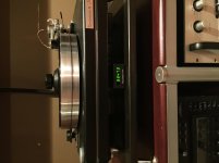
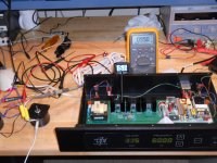
Below is a picture of the SDS connected to the dual motor combination. You can see the output voltage is set for 115VAC, but the SDS is only able to deliver 99VAC as read on the Fluke meter. With the cover off, the heat sink of the output transistors reaches ~150°F after about 1 hour of play. I couldn't touch this with my finger for more than a second without burning myself. I would imagine with the cover in place and no air circulating, the temp rise would be even more. Mind you, this is with no load on the motors.
I also see that HW posted on that thread that only the SDS is capable of driving this motor combination properly. Harry is a really smart guy and his company makes fantastic turntables. Unfortunately, in this case, he is wrong. I connected the SDS up to the same motor combination that I tested the Eagle with (dual 300 RPM 7.5W AC synch motors from Hurst). With the SDS output set to 115VAC no load, the voltage dropped immediately to 99.3VAC after connection. This is most likely due to the choice of output transformer the SDS uses. It is rated at 20W and uses iron core laminations. The Eagle uses a 25W toroid transformer which are known to be stiffer. The SDS also uses a 120-6.3V xfmr which has a turns ratio of ~15:1. The Eagle uses a 120-12.6V xfmr which has a turns ratio of ~8:1. Why does this matter? The impedance seen across a transformer increases as the SQUARE of the turns ratio. Placing a larger load on the output reflects a much lower load to the output amp. By doubling the turns ratio, the SDS increases the load seen by the output amp by 4x. This means the available voltage for the xfmr will sag more, the output amp works harder, and the amount of heat dissipated will increase.
Harry also stipulates that the HRX needs 20W and full voltage to sound correct. If that is the case, then the Eagle should sound better. The Eagle outputs 109VAC into this motor combo or ~13.5W. The SDS is only capable of delivering 99VAC into this combo or a little over 11W. Personally, I don't think reduced voltage will make any difference as long as the motor has sufficient torque to start, and reducing the voltage (on purpose after the platter is up to speed) will only reduce vibration and noise.
The Eagle will drive the HRX turntable with feedback from the tachometer just as well as it does on other tables. There is no reason the control mechanism will break down because of the higher power.
Below is a picture of the SDS connected to the dual motor combination. You can see the output voltage is set for 115VAC, but the SDS is only able to deliver 99VAC as read on the Fluke meter. With the cover off, the heat sink of the output transistors reaches ~150°F after about 1 hour of play. I couldn't touch this with my finger for more than a second without burning myself. I would imagine with the cover in place and no air circulating, the temp rise would be even more. Mind you, this is with no load on the motors.
Attachments
Phoenix Eagle vs VPI SDS
I ran a couple more tests on the SDS power supply over the weekend. One of the things I was curious about was the phase noise (analog jitter) in the reference signal (Fo x 65536) since the output signal at 60Hz is no longer derived from a crystal standard anymore, it is the divided down output of the VCO in a PLL scheme.
One of the reasons to avoid a PLL in this type of circuit, is they all suffer from some amount of phase noise above and beyond the crystal phase noise (which is usually extremely small). The loop filter is a type of delayed feedback and as a result, all VCO's "wobble" about their center frequency depending upon loop bandwidth and noise. The lower the BW, the more they have a tendancy to wobble. The SDS phase detector frequency is 655.36Hz, so the BW of the loop filter will be fairly low.
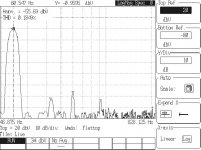
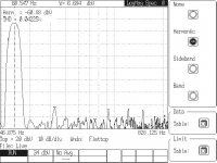
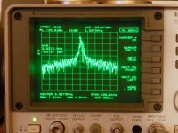
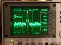
The two attached plots are the spectrum analyzer outputs of the reference signals from the VPI SDS and the Phoenix Eagle. This reference signal is divided down to 60Hz, so the amount of phase noise will be reduced accordingly. The thing to remember is, the cleaner the reference signal, the less phase noise (or jitter) in the 60Hz output. Both pics were shot at the same resolution BW (100 kHz).
The first pic is the SDS with the VCO center frequency of 3.93MHz for 60Hz output.
The second pic is the Eagle crystal reference at 8.388608 MHz for 60Hz output.
Not only is the SDS signal noisier, it also exhibits considerably higher frequency modulation (phase noise). Some of this could be due to the loop filter and some of it could be power supply noise.
I ran a couple more tests on the SDS power supply over the weekend. One of the things I was curious about was the phase noise (analog jitter) in the reference signal (Fo x 65536) since the output signal at 60Hz is no longer derived from a crystal standard anymore, it is the divided down output of the VCO in a PLL scheme.
One of the reasons to avoid a PLL in this type of circuit, is they all suffer from some amount of phase noise above and beyond the crystal phase noise (which is usually extremely small). The loop filter is a type of delayed feedback and as a result, all VCO's "wobble" about their center frequency depending upon loop bandwidth and noise. The lower the BW, the more they have a tendancy to wobble. The SDS phase detector frequency is 655.36Hz, so the BW of the loop filter will be fairly low.
The two attached plots are the spectrum analyzer outputs of the reference signals from the VPI SDS and the Phoenix Eagle. This reference signal is divided down to 60Hz, so the amount of phase noise will be reduced accordingly. The thing to remember is, the cleaner the reference signal, the less phase noise (or jitter) in the 60Hz output. Both pics were shot at the same resolution BW (100 kHz).
The first pic is the SDS with the VCO center frequency of 3.93MHz for 60Hz output.
The second pic is the Eagle crystal reference at 8.388608 MHz for 60Hz output.
Not only is the SDS signal noisier, it also exhibits considerably higher frequency modulation (phase noise). Some of this could be due to the loop filter and some of it could be power supply noise.
Attachments
- Status
- This old topic is closed. If you want to reopen this topic, contact a moderator using the "Report Post" button.
- Home
- Vendor's Bazaar
- Digital Turntable Tachometer and DDS based PSU