Dear builders and DIY enthusiasts!
Here I would like to introduce You my passive stepped attenuators I build in my spare time and offer for sale.
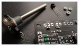
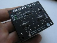
The 8th note Stepped Attenuator has been developed to replace classic potentiometers and mechanical steppers to a higher-end device.
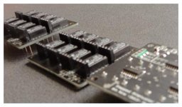
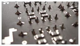
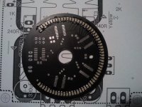
Following the logarithmic ladder attenuator idea, I designed the attenuator to support SMT resistors, making possible to stuff the whole circuit on a compact PCB.
The main advantage is very short routes. The attenuator uses microcontroller and a single potentiometer reading for setting the volume.
No SMT soldering is needed as I pre build every attenuator.
I hope you will like the design and the interface. Purchasing informations are at the bottom if You are interested in buying.
The specification:
-128 logarithmic levels in 0.5dB steps
-high quality 0.1% Susumu SMT resistors installed
-bistable relays with gold plated AgPd contacts
-single potentiometer volume control
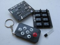
-2 inputs, source selectable with button
-IR remote control receiver (remote supplied)
-1 delayed transistor driven switch - optional
-LULO smart logic controller
-wide power input (10V-20V DC)
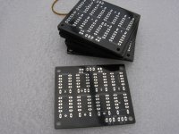
-board dimensions are 50.8 x 58.4mm, complete balanced device is 30mm tall
-all connectors are header compatible
User Manual is available in PDF format. To download user manual follow this link.
The idea was to make a very high quality device, but keeping it simple. Almost minimalistic.
It is DIY friendly, I pre-assemble and test each unit, only few external parts are needed.
-constant input impedance is 10k to support various DACs
-load impedance need to be set (~10k input amps are supported out of the box)
About the availability:
I build in limited numbers. My current run is 6 balanced attenuators.
These are ready to ship in 7-10 days.
I accept PayPal only.
Price: €150 + shipping (approx $200 + Shipping)
Shipping option and cost:
I post worldwide. EMS Express is recommended but to some country I can offer cheaper insured priority mail.
Please ask me about shipping options to your country.
Thank You!
Here I would like to introduce You my passive stepped attenuators I build in my spare time and offer for sale.
An externally hosted image should be here but it was not working when we last tested it.
The 8th note Stepped Attenuator has been developed to replace classic potentiometers and mechanical steppers to a higher-end device.
Following the logarithmic ladder attenuator idea, I designed the attenuator to support SMT resistors, making possible to stuff the whole circuit on a compact PCB.
The main advantage is very short routes. The attenuator uses microcontroller and a single potentiometer reading for setting the volume.
No SMT soldering is needed as I pre build every attenuator.
I hope you will like the design and the interface. Purchasing informations are at the bottom if You are interested in buying.
The specification:
-128 logarithmic levels in 0.5dB steps
-high quality 0.1% Susumu SMT resistors installed
-bistable relays with gold plated AgPd contacts
-single potentiometer volume control
-2 inputs, source selectable with button
-IR remote control receiver (remote supplied)
-1 delayed transistor driven switch - optional
-LULO smart logic controller
-wide power input (10V-20V DC)
-board dimensions are 50.8 x 58.4mm, complete balanced device is 30mm tall
-all connectors are header compatible
User Manual is available in PDF format. To download user manual follow this link.
The idea was to make a very high quality device, but keeping it simple. Almost minimalistic.
It is DIY friendly, I pre-assemble and test each unit, only few external parts are needed.
-constant input impedance is 10k to support various DACs
-load impedance need to be set (~10k input amps are supported out of the box)
About the availability:
I build in limited numbers. My current run is 6 balanced attenuators.
These are ready to ship in 7-10 days.
I accept PayPal only.
Price: €150 + shipping (approx $200 + Shipping)
Shipping option and cost:
I post worldwide. EMS Express is recommended but to some country I can offer cheaper insured priority mail.
Please ask me about shipping options to your country.
Thank You!
Attachments
Last edited:
About the remote logic controller, and LULO function:
Despite the digital controller, the first design rule was to use a single pot for controlling volume instead a rotary encoder or buttons.
A potentiometer gives a specific value when we turn it to a specific position. This is why we like it. (And pots have better looking knobs too with position mark.)
Using a microcontroller also implementing remote control function was possible, but matching that with a single control pot (not motor pot) needs some logic.
The solution is in the controller that handles the switching between the two controls.
When the remote is in use, the controller disables the pot. (The pot will obviously not turn itself to the position where you have been setting the volume with the remote.)
When one turns the pot again, the logic decides whether enable the pot or not based on the position difference between the pot position and the actual volume.
This function prevents accidental volume rise. In case you left the pot in higher position, the LULO light turns off (the name come from voLUme LOck words), and the pot need to be turned down matching the volume position to “lock it” again.
This may sounds weird first, but it is very intuitive once one tried it. This function let us use a single pot for control beside keeping the remote function, and keeps the external costs low. Not mentioning the unique design one can build especially the LULO LED fixed in or behind the pot.
Display upgrades:
Displays can be designed and built for the attenuator. It could be a nice DIY project!
This is a DIY community so no surprise, it needs some work.
Harvesting data from the attenuator is done at two headers, the LED headers (LO-HI), and the DO header (SPI).
Connecting a separate MCU module to these headers, it is possible to display the attenuation level (0-64dB) and functions like the selected channel.
You can build seven segment displays, or LED rows at low costs.
I am making a documentation with examples in the next days, Offering programmed chips possibly, but first I need some feedback if there is any demand for a display controller.
This is a very nice design, I want one. When funds permit soon I shall get an SE set.
The display controller is a good idea, the attenuator outputs spi right? How hard would it be to use an LCD phone type display? (nokia type) I am learning arduino and Eagle at the moment and thought the display controller would be a nice project to try. Might hit you up for some advice when I get one.
Good blog by the way especially tips on beginning projects.
Making displays for the 8th note attenuator needs a microcontroller or Arduino board.
I know it is not entirely about audio but there are close as DIY made for audio (enclosures).
Hereby I will cover the essentials, and possibilities. I try to make it beginner friendly.
Even if you are not familiar with programming, it is nice to understand what is behind.
But what is possible at the first place?
a) Using the LED headers without any additional circuit status LEDs can be mounted as an indicator on the faceplate or as backlight.
b) With additional circuits, it is possible to make a LED bar turn on and follow the level of attenuation (volume).
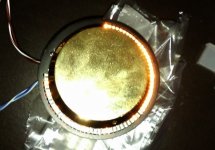
c) When doing this with a lot of leds, mounted around the pot itself it can even follow the pot position.
d) The last solution could be a character display with seven segment LED displays, or a more advanced text based character display.
e) Any cool idea.
The a) is already covered by the documentation, it needs no additional parts but the LEDs.
The d) is out of the scope of this text but the piont is, you can do whatever you want when you already get some data out. Lets see how.
Getting information out of the attenuator is possible on two headers:
1. LED header
2. DO header
1. The LED header is the simplest, with a state check, a pin next to the LED can be checked against GND.
This can tell the same information as the LED status. Thus we can read which channel is selected, if mute has been pressed, or if LULO is on (pot or remote is master).
Later we can use this information as variables (true or false) in our program, and do whatever we want. Turn on lights, or send a message to a display.
To a microcontroller it is as simple as it gets:
2. The DO header is an SPI communication port that outputs a coded word on each volume change. This code can be decoded to get the attenuation level 0-127 or 0dB-64dB.
The data can be read with a microcontroller, and processed to get a single number variable. It is something like...:
If we have the attenuation level, we can easily do actions according to it:
Lets see if we have a LED bar like this (Seed Grove LED bar).
It has 10 LEDs. Let it have the bottom red LED indicating only the level 0 or MUTE. So we have 9 LEDs left for indicating 127 levels. Easy math, 127 / 9 = 14,11 so we will have one LED for every 14 setting.
Actually we will have one LED for level 1, 14, 28, 42, 56, 70, 84, 98, 112, 126
Now you only need a small code that checks the current level, and light up LEDs according to that level.
For a real circuit, you need transistors or a LED driver too, because no microcontroller outputs are designed to drive LEDs.
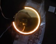
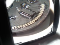
Using lots of LEDs in a circular arrangement is very cool. See the attached images for a real example.
It is an advanced version of the above, that is only one example prototype.
I know it is not entirely about audio but there are close as DIY made for audio (enclosures).
Hereby I will cover the essentials, and possibilities. I try to make it beginner friendly.
Even if you are not familiar with programming, it is nice to understand what is behind.
But what is possible at the first place?
a) Using the LED headers without any additional circuit status LEDs can be mounted as an indicator on the faceplate or as backlight.
b) With additional circuits, it is possible to make a LED bar turn on and follow the level of attenuation (volume).
c) When doing this with a lot of leds, mounted around the pot itself it can even follow the pot position.
d) The last solution could be a character display with seven segment LED displays, or a more advanced text based character display.
e) Any cool idea.
The a) is already covered by the documentation, it needs no additional parts but the LEDs.
The d) is out of the scope of this text but the piont is, you can do whatever you want when you already get some data out. Lets see how.
Getting information out of the attenuator is possible on two headers:
1. LED header
2. DO header
1. The LED header is the simplest, with a state check, a pin next to the LED can be checked against GND.
This can tell the same information as the LED status. Thus we can read which channel is selected, if mute has been pressed, or if LULO is on (pot or remote is master).
Later we can use this information as variables (true or false) in our program, and do whatever we want. Turn on lights, or send a message to a display.
To a microcontroller it is as simple as it gets:
An externally hosted image should be here but it was not working when we last tested it.
2. The DO header is an SPI communication port that outputs a coded word on each volume change. This code can be decoded to get the attenuation level 0-127 or 0dB-64dB.
The data can be read with a microcontroller, and processed to get a single number variable. It is something like...:
An externally hosted image should be here but it was not working when we last tested it.
If we have the attenuation level, we can easily do actions according to it:
Lets see if we have a LED bar like this (Seed Grove LED bar).
An externally hosted image should be here but it was not working when we last tested it.
It has 10 LEDs. Let it have the bottom red LED indicating only the level 0 or MUTE. So we have 9 LEDs left for indicating 127 levels. Easy math, 127 / 9 = 14,11 so we will have one LED for every 14 setting.
Actually we will have one LED for level 1, 14, 28, 42, 56, 70, 84, 98, 112, 126
Now you only need a small code that checks the current level, and light up LEDs according to that level.
For a real circuit, you need transistors or a LED driver too, because no microcontroller outputs are designed to drive LEDs.
Using lots of LEDs in a circular arrangement is very cool. See the attached images for a real example.
It is an advanced version of the above, that is only one example prototype.
Attachments
I would like to show off my newly acquired 8th Note Attenuator, an excellent design that has been very finely assembled by Laci, possibly one of the nicest pieces of electronic kit I have bought.
The service, support and documentation by Laci is also exemplary, I am seriously impressed and just a little jealous that I cannot design something like this myself... one day")
I will be powering this with an AMB 12V regulator board combined with a Myrra 2VA transformer and have already purchased the Grove LED bar mentioned above and a OLED 126 x 62 display to experiment with.. I also have spare sample atmega8 and attiny45 micro controllers for the display, hopefully the tiny45 will be good enough for this.
I'm delighted and highly recommend this attenuator, the product is superb and the designer is a gentleman... what more could you ask.
The service, support and documentation by Laci is also exemplary, I am seriously impressed and just a little jealous that I cannot design something like this myself... one day
I will be powering this with an AMB 12V regulator board combined with a Myrra 2VA transformer and have already purchased the Grove LED bar mentioned above and a OLED 126 x 62 display to experiment with.. I also have spare sample atmega8 and attiny45 micro controllers for the display, hopefully the tiny45 will be good enough for this.
I'm delighted and highly recommend this attenuator, the product is superb and the designer is a gentleman... what more could you ask.
Attachments
Last edited:
SINGLE ENDED ATTENUATOR
Hi there,
I am still not lost. But most of the attenuators are gone. Thank You!
Just want to know, I still have 3 SE (not Balanced) attenuators ready.
Last chance to get them in 2013.
(Also 2 SE makes one Balanced attenuator, but hurry up for those.)
Please contact me if You are interested.
Hi there,
I am still not lost.
But most of the attenuators are gone. Thank You!Just want to know, I still have 3 SE (not Balanced) attenuators ready.
Last chance to get them in 2013.
(Also 2 SE makes one Balanced attenuator, but hurry up for those.)
Please contact me if You are interested.
Hi there,
Because of some requests,
I am offering a free relay PCB for those who buy one of the remaining 3 SE attenuators, and want to build a balanced one. Part list is included with the unpopulated PCB. If you are willing to do a little work, you get a professional stepped attenuator for a real bargain.
Because of some requests,
I am offering a free relay PCB for those who buy one of the remaining 3 SE attenuators, and want to build a balanced one. Part list is included with the unpopulated PCB. If you are willing to do a little work, you get a professional stepped attenuator for a real bargain.
Last edited:
Hello Johnny2Bad,
I appreciate Your interest in the attenuators, and Your intent on building one for Yourself. This is diy audio after all! However I only can tell now that I am going back to this topic later when I can work on the attenuator design again, hopefully around end of this year.
I appreciate Your interest in the attenuators, and Your intent on building one for Yourself. This is diy audio after all!
However I only can tell now that I am going back to this topic later when I can work on the attenuator design again, hopefully around end of this year.- Status
- This old topic is closed. If you want to reopen this topic, contact a moderator using the "Report Post" button.
- Home
- Vendor's Bazaar
- 8th note Balanced Stepped Attenuators