Power transformer and enclosure arrived. I have just installed missing parts and everything is working. But I am concerned about one thing, during turning off I measure 1.9V DC transient at output with nothing connected, and about 500mV with junk test earphones. After spike, it is slowly falling. When amp is working everything is fine, DC offset is under 1mV. Same with no source connected. It should be like that, and is it safe to connect my Beyers?Very nice work indeed! You're a natural when it comes to SMD work
As for the tab of Q3, it is indeed electrically connected to GND on the board itself, so it is expected that you will measure close to 0 ohms between the tab and heatsink even if the insulator is properly mounted. This can be seen in the schematics.
This is not true for Q4 however, as this reg has its output connected to GND and needs to be open circuit from tab to heatsink.
Looks like you're good to power it up!
Let us know how it turns out.
Cheers,
Owen
Q&A Time!
You bet! The amplifiers are completely done, tested, and ready to go. The hold up is me saving up enough money to do a production run of about 50 units.
The website is also in the works, so it's just a matter to timing everything and doing an official release.
It is getting very close now though.
The ES9018 is used for the DAC itself. Some of the details are in the first post of this thread.
That transient sounds quite high compared to what I've seen on my unit. It's not going to be an issue for larger Beyer phones, but it seems to imply there is an issue somewhere.
A few questions:
1. Are you using the correct "PSU V2" and the suggested output caps and output voltage?
2. Is this with a source connected or with the input floating?
3. How are you measuring this? Scope? DMM?
4. The load on the output shouldn't really have much impact on the startup or shutdown transient, so I'm curious about why it went from 1.9V down to 500mV with a load.
5. Is it swinging positive or negative?
6. Is it the same every time?
Regards,
Owen
"It's very close to being ready for release." Same with assembled amps?
You bet! The amplifiers are completely done, tested, and ready to go. The hold up is me saving up enough money to do a production run of about 50 units.
The website is also in the works, so it's just a matter to timing everything and doing an official release.
It is getting very close now though.
Which dac is used in your project Owen ?
The ES9018 is used for the DAC itself. Some of the details are in the first post of this thread.
Power transformer and enclosure arrived. I have just installed missing parts and everything is working. But I am concerned about one thing, during turning off I measure 1.9V DC transient at output with nothing connected, and about 500mV with junk test earphones. After spike, it is slowly falling. When amp is working everything is fine, DC offset is under 1mV. Same with no source connected. It should be like that, and is it safe to connect my Beyers?
That transient sounds quite high compared to what I've seen on my unit. It's not going to be an issue for larger Beyer phones, but it seems to imply there is an issue somewhere.
A few questions:
1. Are you using the correct "PSU V2" and the suggested output caps and output voltage?
2. Is this with a source connected or with the input floating?
3. How are you measuring this? Scope? DMM?
4. The load on the output shouldn't really have much impact on the startup or shutdown transient, so I'm curious about why it went from 1.9V down to 500mV with a load.
5. Is it swinging positive or negative?
6. Is it the same every time?
Regards,
Owen
1. PSU V2, parts as suggested earlier in thread. Output voltage is standard 15V, reading 14.98V / -15.11V
2. Nothing connected to RCA sockets.
3. Cheap ~10 USD DMM
5. Negative
6. Tested several times a minute ago, 830mV and about 150mV with phones then slowly falling so it looks much better now. Powering on of course brings 1mV immediately. I don't know why it vary so much from last result.
If it relevant, i'm using 100k Alps pot, as suggested changed R14&R18 to 1M Ohms and shorted R13&R17. Tommorow i will check second kit which i had assembled.
Sorry to report this, I'm having the same problem with the PSU v2 and SE-SE amp on shutdown. PSU v2 built as per BOM, input/output caps are 2700uF not 3300uF versions of the correct Nichicon caps.
SE-SE has been used for roughly 18 months with PSU v1. Built V2 last night, double checked everything and wired into place this morning... Measured with a DMM.
PSU v2 first power up ... not connected to SE-SE; ~ +/-15.2Vdc ... on switch off the rails appear to stay high for a long time before dropping [larger caps & no load?].
PSU v2 connected to SE-SE, No output load & no input source connected; Power on and running, DC offset is <1mV ... Shutdown DC offset on both channels spike at -2.4 to -1.6 Vdc, but stay >200mV for ~10 seconds.
PSU v2 power down connected as above ... Rails drop from +/-15V after ~ 1 second. Negative rail settles at ~ -1.5Vdc & Positive rail settles at ~ -0.5Vdc.
With 22R 7Watt dummy load ... power down DC offset spikes at ~ 1Vdc and drops to <10mV in <5 seconds.
With 180R 3Watt dummy load ... power down DC offset spikes at ~ 1.7Vdc and drops to <10mV in <5 seconds.
Paul.
Hi Paul,
Thanks for the thorough evaluation! I was wondering if the strange behavior was a result of the cheap DMM BamboszeK was using as they can sometimes give strange results when measuring a transient.
I will look into this on Monday and get a few scope captures to see what's going on. This obviously isn't desirable behavior but given the relatively low loaded voltage and short duration, it's still certainly safe to use them as is for now.
I'll characterize what's going on and see if there's a way to remedy it. The solution might be as simple as either smaller or asymmetrical output filter caps on the PSU.
Cheers,
Owen
Thans for reply. Actually as you said it is not a big deal for bigger headphones, but with IEMs pop sounds a bit dangerous
I'm using exactly these caps: EKZH250ELL272MK35S United Chemi-Con | Mouser
I'm using exactly these caps: EKZH250ELL272MK35S United Chemi-Con | Mouser
Couldn't find any anomalies and took a chance on plugin-in the Senn HD-650s... There is a 'Tick' on power up and 'Pshhh...' on powering down, but not at a level I'd consider damaging to the phones. So full speed ahead.
Thanks for all the time and effort your putting into this Owen, very much appreciated
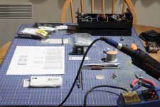
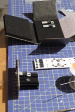
Pic's 1-3; getting ready to build the PSUs. Needed to bend the legs of the regs myself, and just about to fit the new PSU...
Very hard to comment on what changes occurred [if any] on swapping PSUs, maybe a touch cleaner through the bass registers. Without a direct A/B comparison it's a very tough call...
Paul
Thanks for all the time and effort your putting into this Owen, very much appreciated
Pic's 1-3; getting ready to build the PSUs. Needed to bend the legs of the regs myself, and just about to fit the new PSU...
Very hard to comment on what changes occurred [if any] on swapping PSUs, maybe a touch cleaner through the bass registers. Without a direct A/B comparison it's a very tough call...
Paul
Attachments
Hi Owen,
I received my PCBs 2 days ago, very nice and I love the white mask.
Where can I get the latest BoM for The Wire SE-SE and PSU for the latest PCBs?
Thanks
Do
I guess my question got ignored... Would be nice if the latest BoM was always on the first post of its respective thread.
Thanks
Do
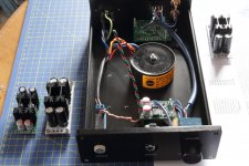
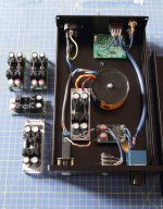
Forgot to add the picture of the fully wired SE-SE with new PSU and a few extras... not my tidiest build but works a treat.
Totally amazed by the clarity of detail and overall performance of this setup, certainly not left wanting for sure... However, am intrigued to find out how the BAL-BAL and a better DAC sound
Totally amazed by the clarity of detail and overall performance of this setup, certainly not left wanting for sure... However, am intrigued to find out how the BAL-BAL and a better DAC sound
Attachments
Here is my one - The Wire by BamboszeK - Imgur
First I wanted to use a potentiometer, but later I abandoned that idea and i'm using volume control at DAC
First I wanted to use a potentiometer, but later I abandoned that idea and i'm using volume control at DAC
- Home
- Vendor's Bazaar
- "The Wire" Official Boards for All Projects Available Here! BAL-BAL, SE-SE, LPUHP