Hi, just put a CRD device (current source/sink) between rail and base, then a Zener between base and output.
This is the same kind of approach that is used for the AMBlaboratoroies Beta 22 (and 24) where you might have a look")
also NPass did some experimentation about this and I remember a PDF somewhere...
cheers
This is the same kind of approach that is used for the AMBlaboratoroies Beta 22 (and 24) where you might have a look
also NPass did some experimentation about this and I remember a PDF somewhere...
cheers
Hi, just put a CRD device (current source/sink) between rail and base, then a Zener between base and output.
This is the same kind of approach that is used for the AMBlaboratoroies Beta 22 (and 24) where you might have a look
also NPass did some experimentation about this and I remember a PDF somewhere...
cheers
Hi and thanks for the advice. That Beta22 is very interesting, though more complex. The nice thing about the VSSA is contained in his name.
I am fully sold to cascoding.
Next is cascoding all stages and then paralelling output devices with higger PS rails.
All the best,
M.
yeah managing to linearize all stages is good and the basis, but still do not under estimate the importance of Loopgain (nfb) to get all the residual out, (with high slewrate).
from my side, I m working on Composite amplifier based on CFA+opamp. kind of "alexander amp" this outperform while providing stable bias, controled tempco and very low offset (5mv) without trim.
Just start from Alexander amp, put wilson current miror on each rail, a simple resistor for bias control and a pair of lateral mosfet. then choose a symetrical opamp like LT136x or AD844 and a global feedback loop between output and in- of the op amp.
Last edited:
Interesting ideas.Not that I understand everything you comment...
Anyway, more complex topologies tend to "sound" more "analytical" generally, so we want to keep in mind that involving sound reproduction is our goal...I mean, sometimes a more elegant technical solution sounds worse than the simplest, bulkier, uglier, inefficient way...that is why we have to take the time to evaluate each step sound-wise.
Cascoding the outputs makes sense to me because the physically bigger output units have also bigger BC (GD) capacitance...
Je vous souhaite la meilleure des chances.
M.
Looking for FirstOne 1.4M module
Hi !!
I just fried (half working, bad sound, 2 led lights still on) a FirtsOne V1.4M module of my dual-mono amplifier.
No answer so far from Ubiq .......
I'm just asking for someone having a spare one for selling .........
PM me here if so!
Thanks in advance
JMK
Hi !!
I just fried (half working, bad sound, 2 led lights still on) a FirtsOne V1.4M module of my dual-mono amplifier.
No answer so far from Ubiq .......
I'm just asking for someone having a spare one for selling .........
PM me here if so!
Thanks in advance
JMK
VSSA as preamp/driver
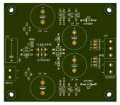
I have started a build of the earliest VSSA that deletes the OPS and deletes the bias spreader. The application is to have a driver for testing out other OPS configurations. Something for the bench for now and possibly for a final design eventually. With the parts I have selected, I can crank the voltage up higher than most conventional preamplifiers if needed.
I have parts on hand so if I burn a part there is no harm done.
Thanks, LC, for this circuit.
Attachments
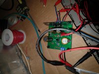
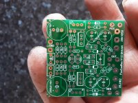
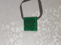
Built PCB
Finally have all the parts, matched transistors, no matching of resistors.
+ / - 35V rails. 3mV DC output offset. 2.2mA bias front end. 10mA bias second stage.
Output impedance 55-ish ohms.
Better than 60v p-p before clipping.
Bandwidth is insane. -3dB 14.3 MHz with a peak 10-ish MHz. Phase is quite wonky out in the MHz space.
Good enough to use as a driver for various OPS experiments.
Front end devices are 2SA970BK/2SC2240BL
Output devices are KSA1381E/KSC3503E.
Attachments
Good front-end for transient transfer, no frequency peaking, no ringing, compensate for phase margin to be at least 90 deg at 0 dB to be stable.Good enough to use as a driver for various OPS experiments.
To put this kind of amp in high-end realm, OLG should be 100 dB or more, by maintaining speed and stability, and that is a challenge probably unreachable with such simple circuit.
Great work.
Cheers, L.C.

Hitachi did an app note amplifier which was very popular.
Maplin copied it for their own 74 watt lateral mosfet amp.
Maplin copied it for their own 74 watt lateral mosfet amp.
An externally hosted image should be here but it was not working when we last tested it.
Lateral MOS still available in the market?
I don't find noone of them listed in this thread
Try harder, Exicon makes a whole range of them, they’re the 2nd search result if you type ‘lateral mosfet’ in Google.
Lateral MOS still available in the market?
I don't find noone of them listed in this thread
Profusion PLC has a good range and they also sell a double die high current variety.
TCD
Last edited:
which of the V1.1´s do you have? there seem to be many layouts.are these an option ?
After many years of staying away ive come back to this drsign and plan on building a new amp with it. The thing that worries me tho is the robustness of the circuit. Vssas i built in the past would all let out magic smoke if the input rca was pulled out and reinserted while the amp was on. The burning component was found to be the 10 ohm resistors that filter the rails. Im rather rough with my equipment so this accident happens quite often and its why vssa suffered many deaths and eventually never revived again. On my new build id like to make sure the amp can withstand any kind of user errors so id like to know what i should add to the circuit (voltage divider before the input cap maybe?) or whether vssa was even vulnerable to these issues or it was my construction fault. (The grounding was always bad in my vssa and since then i have learned better methods)
- Home
- Vendor's Bazaar
- VSSA Lateral MosFet Amplifier