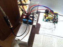
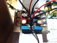
Wow,Maybe is the angle of picture, but those terminals look way too close to those caps. Do you have enough room to connect power to those terminals?
Ya, they're quite close but still manageable.
")
I just received 2 sets of SMPS500R from connexelectronic and parts from Farnell. Looks like this few days need OT to complete it.
An externally hosted image should be here but it was not working when we last tested it.
James
Is this voltage between TP1 and TP2? If yes, than OK.
Thanks, Lazy.
2 sets of SMPS500R from connexelectronic
James
 I wonder how do they compare to hypex ones.
LC all those meet what you said. (except last one maybe being 11V drop) I did something to it, have no idea what but plugged it another time and... it worked! And calibrated in 5 mins to get 120mV bias with 0mV on output and 4V on resistor! Working on another channel and then going to some rehearsal
but plugged it another time and... it worked! And calibrated in 5 mins to get 120mV bias with 0mV on output and 4V on resistor! Working on another channel and then going to some rehearsal Congratulations Renio you've made it running. I'm glad you like it.
I have experience with Hypex SMPS only, so cannnot comment. But I think non regulated 50 % duty-cycle is best what I have heard. PSU regulation can be invasive to amp's sound if it's not optimal. People sometimes report it as slow, uninvolving sound gained from that kind of PSU.
Try and report, regards
Thanks Patrick and Andrej.
Andrej I need your help, I have the SSA DC SENSE from Supernet (another Andrej
Hi Junie

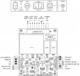
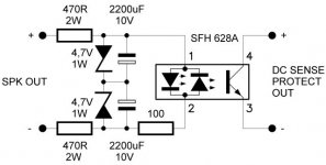
Here's what would help you out. DC Sense Protect out connect to Connector C pin 6, 8.
Attachments
Logical experimental step would be VSSA BIGBT and that's exactly on the menu at the moment.
Today's play, VSSA BIGBT with four bipolar outputs up and running. 76 Vpp max on the output when no load connected. Than 4 Ohm load connected and still 76 Vpp on the output, frequency 10 Hz, meaning 180 Wrms/4 Ohm. BIGBT-s connected to VSSA PCB without any compensation modification, no oscillations whatsoever, -3dB/3 MHz bandwidth preserved hehe.
Attachments
Could someone email me the instructions. Plan to fire it up today, but my instructions wee torn and now gone.
Hi Justin
Installation Manual attached.
Attachments

I have a similar monobloc in design! [Reason being to use short speaker cables and long interconnects. (Otherwise they have to live in a poorly ventilated cupboard!)]
Do you intend to have a ventilation slot below and above the amp. PCB?
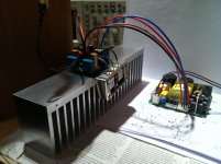
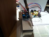
This is just a test chassis it will remain as showned on picture. Heatsink are visually damage and shown many drill => was heatsinking TO3 devices. So it's perfect for test but not for definitv housing.
Marc
Hi Junie
Here's what would help you out. DC Sense Protect out connect to Connector C pin 6, 8.
Hi Andrej,
Thanks!
I will connect DC sense (L and R) in parallel to Conn. C pin 6 & 8?
Cheers,
Junie
My JC-80 is ready to feed the VSSA. Also, my VSSA modules are ready to be mounted, feed and testing. Still need to decide what to use as the power supply... A toroid that is a bit on the small side (250VA) with 4 separate 28V windings, or a bigger one (500VA) with similar 4x 28V windings. It depends also on the internal size of the case.
@LC, can you please post some details?
Cheers!
@LC, can you please post some details?
Cheers!


- Home
- Vendor's Bazaar
- VSSA Lateral MosFet Amplifier