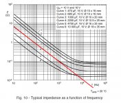
Considering the following curve (attached) and splitting the feedback 47 ohm resistance in two, one for the electrolytic to ground, one for the film cap to ground, i'm sure you can have several advantages: better linearity (no added resonances) and smaller film cap (with less inductance at HF, less surface, less price).
I know you can feel i'm a little maniac about it, but, based on my experience, it makes a noticeable difference in listening experience, as it was said in the SSA thread by some Diyers, witch preferred the electrolytic cap alone.
I know you can feel i'm a little maniac about it, but, based on my experience, it makes a noticeable difference in listening experience, as it was said in the SSA thread by some Diyers, witch preferred the electrolytic cap alone.
Attachments
Last edited:
Considering the following curve (attached) and splitting the feedback 47 ohm resistance in two, one for the electrolytic to ground, one for the film cap to ground, i'm sure you can have several advantages: better linearity (no added resonances) and smaller film cap (with less inductance at HF, less surface, less price).
I know you can feel i'm a little maniac about it, but, based on my experience, it makes a noticeable difference in listening experience, as it was said in the SSA thread by some Diyers, witch preferred the electrolytic cap alone.
It is not practical to split.
What you want is to have a low impedance over the frequency band up to MHz region. Thats why we parallel them. But to avoid the resonance or at least damp it. We could add a 1R resistor in series with the elcap.
If you extend the curve to 10MHz you see that the impedance starts to rise again.
Of course and that is all about. I know it is not easy, and need some real world experiment, but it is less critical than in the direct signal path, because any increase of the impedance increase the feedback, so reduce the gain at Hf, where we have no so much need ;-)It is not practical to split.
What you want is to have a low impedance over the frequency band up to MHz region. Thats why we parallel them. But to avoid the resonance or at least damp it. We could add a 1R resistor in series with the elcap. If you extend the curve to 10MHz you see that the impedance starts to rise again.
My idea, here, is to find the resonance of the electro cap then add a // RC with a little film cap ( 0.1µF or so ? ), just to linearize here and upper.
But the other way is just to forget the film cap, electrolytic are not so "evil".
Of course and that is all about. I know it is not easy, and need some real world experiment, but it is less critical than in the direct signal path, because any increase of the impedance increase the feedback, so reduce the gain at Hf, where we have no so much need ;-)
My idea, here, is to find the resonance of the electro cap then add a // RC with a little film cap ( 0.1µF or so ? ), just to linearize here and upper.
But the other way is just to forget the film cap, electrolytic are not so "evil".
yes you right. It is just as good to do it on a filmcap.
But the sound without elcaps in the signal path is better!

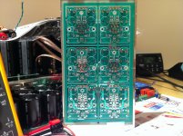
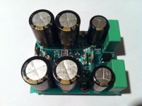
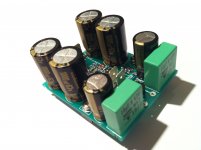
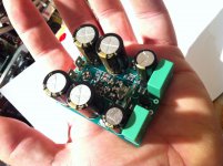
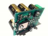
VSSA 1.4 PCB final version. Miller capacitors, offset and bias setting resistors on the top, to be easy accessible and tuned to the exact value. No trimmers for no-compromise long term reliability. Output RC filter splitted in to two ways to have better power dissipation since SMDs are used.
Have fun.
Can`t go much smaller than this...goodbye fuses
All VSSA parts got their positions on the PCB in the first phase, their optimal values will be fully investigated in the second phase of the testing. Feedback resistors values will likely be elevated to 2,2k/100R or something in between, depends on lower roll-off target. Power dissipation of certain resistor can be increased simply by paralleling/stacking them on top of each other. Specific Vishay SMD resistor case can handle 1W by default and can be increased to 5W as explained, if needed at all.
L.C., I have no idea of the real impact of this so called resistance distortion on listening and measurements, as i never made any exploration of this problem. May-be just an other 'audiophile' evil ?
Anyway, with such high bandwidth amps, and in this critical path, paralleling the resistances (lower reactance) can only have positive effects
Anyway, with such high bandwidth amps, and in this critical path, paralleling the resistances (lower reactance) can only have positive effects
Last edited:
All VSSA parts got their positions on the PCB in the first phase, their optimal values will be fully investigated in the second phase of the testing. Feedback resistors values will likely be elevated to 2,2k/100R or something in between, depends on lower roll-off target. Power dissipation of certain resistor can be increased simply by paralleling/stacking them on top of each other. Specific Vishay SMD resistor case can handle 1W by default and can be increased to 5W as explained, if needed at all.
Most SMD types need space of copper connected to the pins (in the same way as power mosfets and transistors) to get rid of the heat. So stacking will only increase the heat handle a little.


May we have comparative listening impression with your SSA ? I know you are very good in this disciplineI don't know if that kind of interest really exists
I'm especially interested to get some inputs about any differences in signature between power lateral MOSFETs and BJTs.
I don't know if that kind of interest really exists
I expect the results will be better than in prototyping phase. Will do most of the job over the weekend.
Regards L.C.
If result satisfy you i think to take 12 u (7u me et 5u a friend)
Marc
How cool is this guys?
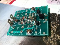
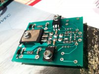
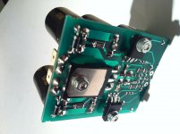
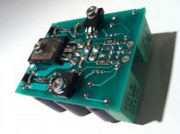
One VSSA channel done, one more to go.
One VSSA channel done, one more to go.
Attachments
-
 VSSA PCB 4.jpg620.1 KB · Views: 2,552
 -
 VSSA PCB 5.jpg480.2 KB · Views: 2,342
 -
 VSSA PCB 8.jpg418.6 KB · Views: 1,372
 -
 VSSA PCB 7.jpg919.3 KB · Views: 1,654
 -
 VSSA PCB 9.jpg392.3 KB · Views: 920
 -
 VSSA PCB 10.jpg360.5 KB · Views: 766
 -
 VSSA PCB 11.jpg458 KB · Views: 909
 -
 VSSA PCB 12.jpg968.9 KB · Views: 1,064
- Home
- Vendor's Bazaar
- VSSA Lateral MosFet Amplifier