Member
Joined 2009
Paid Member
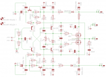
I don't understand the caps after the current sources...VSSA 1.4 Schematic final version
I don't like parallel film caps with electrolytic neither unless some inductance or resistance between them to dump the resonance..
Last edited:
I don't understand the caps after the current sources...
I don't like parallel film caps with electrolytic neither unless some inductance or resistance between them to dump the resonance..
These capacitors form feedback AC ground, without them amplifier is not working properly. Two in parallel to cover bandwidth currents in low Z.
")
So, you have a current source for DC only ?These capacitors form feedback AC ground, without them amplifier is not working properly. Two in parallel to cover bandwidth currents in low Z.
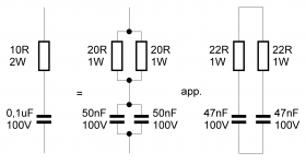
Do not believe that paralleling film and electrolytic caps reduce the Z at HF, it is exactly the opposite.
They make a resonant circuit with the inductance of the electrolytic situated inside the bandwidth of the amp. One of the reason some found SSA was sounding better without the film.
And, may-be, why you have this hard to dump ringing with capacitive load ?
It's looking good
Yes indeed, it also measures very good and it is unconditionally stable. I intentionally overloaded it with 2,2 uF at 100 kHz squares without load's real component and it survived with distortions only. No output noise noticable.
No it handles every possible micro current mudulations, the ones resistor cannot at least to such low levels. Tested.So, you have a current source for DC only ?
Capacitor on output leads is sort of a short circuit linearly going down to zero with frequency rising. Since squares are row of harmonic structure, capacitor's impedance slowly eliminates high order harmonics and the result is distorted squares. Perfectly normal plot result.why you have this hard to dump ringing with capacitive load ?
You had no protective inductance and resistive load when you did the square test ?Perfectly normal plot result.
About // capacitances, some useful links:
Some useful links:
http://www.hagtech.com/pdf/snubber.pdf
http://www.ti.com/lit/an/sloa069/sloa069.pdf
http://www.n4iqt.com/BillRiley/multi/esr-and-bypass-caps.pdf
Impressive ! Congratulations, as habit.No output serial inductance, only 8 ohm load resistor and 0,22 uF parallel to the load when performing 50 kHz squares test.
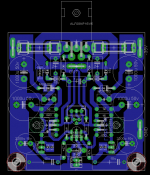

Missing tracks on the FET CSSs ?Preliminary VSSA PCB 1.4, 50 x 60 mm
Missing tracks on the FET CSSs ?
It is not finished yet. I went to sleep before ending. Today it will be done.
VSSA 1.4 MosFet Amplifier PCB
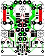
VSSA 1.4 PCB final version. Miller capacitors, offset and bias setting resistors on the top, to be easy accessible and tuned to the exact value. No trimmers for no-compromise long term reliability. Output RC filter splitted in to two ways to have better power dissipation since SMDs are used.
Have fun.
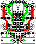
Attachments
VSSA 1.4 PCB final version. Miller capacitors, offset and bias setting resistors on the top, to be easy accessible and tuned to the exact value. No trimmers for no-compromise long term reliability. Output RC filter splitted in to two ways to have better power dissipation since SMDs are used.
Have fun.
What value have you use than?
Marc
- Home
- Vendor's Bazaar
- VSSA Lateral MosFet Amplifier