how better is THD with CCS? Reduced 3rd harmonic?
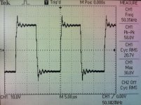
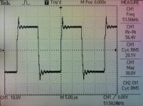
Didn't measure, but you can get quick impression by comparing these two.
")
Before and after.
Attachments
Lazy Cat;3313485What do you think about loaded VSSA's squares response? :rolleyes:[/QUOTE said:
Last edited:
It is a forum's bug: nothing appears in the editor.Esperado, images-links not working. Can you repeat-repair?
Didn't measure, but you can get quick impression by comparing these two.
Before and after.
And the simplicity with CCS?? I could not resist to ask!
If performance and sound is improved by the add of 2 litle FETs and 2 resistances, not in the signal path, what do you chose ?And the simplicity with CCS?? I could not resist to ask!
If performance and sound is improved by the add of 2 litle FETs and 2 resistances, not in the signal path, what do you chose ?
Agree. I only wrote so because if i have come up with an suggestion i got the message "It has to be simple.. Only 6 transistors, that is what it is going to be..."
Agree. I only wrote so because if i have come up with an suggestion i got the message "It has to be simple.. Only 6 transistors, that is what it is going to be..."
Resistors were there already, so two fets added only.
But it is possible to replace 15 k resistors with 1N5307 (2,4 mA CRD), so still six transistors VSSA hehehe.

Attachments
Last edited:
Resistors were there already, so two fets added only.
But it is possible to replace 15 k resistors with 1N5307 (2,4 mA CRD), so still six transistors VSSA hehehe.
Seems quite hard to purchase....
Marc
Resistors were there already, so two fets added only.
But it is possible to replace 15 k resistors with 1N5307 (2,4 mA CRD), so still six transistors VSSA hehehe.
Seems quite hard to purchase....
Marc
If performance and sound is improved by the add of 2 litle FETs and 2 resistances, not in the signal path, what do you chose ?
I think one of my suggestion in this thread in the begining was to replace them with an CCS.
Main reason to have a more constant current to the input pair over supply voltage.
Fets are ok. But they are not common up to more than 35V bvdss
They are used in the TSSA also. but it is conjuction with an bipolar transistor.
Sonny we cleared about CCS in SSA, here's the same.
My intention was on purpose to check behaviour with current injection resistors as I explained detaily before why. For CCS I could drawn them in the first sch pic, but as I said, current injection resistors here have so special position that they deserve prime design. Also from comparisons plots you can see that the difference is so small, all in all very good result for one to use resistors only and VSSA sounds great with them too.
CCS brings a little extra to the whole picture.
Wrong? 2N5462, Vds=40 V
Attachments
A J-Fet cascode can stand more voltage, so does a MosFet like the DN2540.
I modified the TSSA with CCSs and the sound improved much. I think you should include the CCS although we have then more then 6 transistors.
It could be argued that the CCSs are not direct in the signal path. OK, not a very strong argument but missing this chance of improvement is stupid too.
I modified the TSSA with CCSs and the sound improved much. I think you should include the CCS although we have then more then 6 transistors.
It could be argued that the CCSs are not direct in the signal path. OK, not a very strong argument but missing this chance of improvement is stupid too.
Last edited:
There is plenty of good amps, simple or less simple. I know some Audiophiles believe that simple is beautiful. It is not always true
I believe that each improvement with real benefit, even at the price of a little added complexity, need to be evaluated. It will cost little more $ and time during building, but who care, several months after, when you listen music ?
And, we all know L.C., here, he begin with 6 transistors, and will finish with 12
Last edited:
Sonny we cleared about CCS in SSA, here's the same.
My intention was on purpose to check behaviour with current injection resistors as I explained detaily before why. For CCS I could drawn them in the first sch pic, but as I said, current injection resistors here have so special position that they deserve prime design. Also from comparisons plots you can see that the difference is so small, all in all very good result for one to use resistors only and VSSA sounds great with them too.
CCS brings a little extra to the whole picture.
Wrong? 2N5462, Vds=40 V
That is the one an only .. more or less.
My favorite is the J110 - J112 : 6 times lower noise level...
But some manufactures says 35V and others 40V. So i believe more on the 35V
Jfet PMBF4391 - 4393 is rated at 40V from NXP and 30V from ONSEMI.
I had put BF245 for simple CCS with success in the early SSA experiments. Has low capacitance and good noise. Just another through-hole part option.
I remember well.I think one of my suggestion in this thread in the begining was to replace them with an CCS.
I have no experience with CRDs. How good (and fast) are they ?
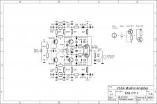
VSSA 1.4 Schematic
VSSA 1.4 Schematic final version from which I wish to design PCB. Should be two layered, very compact PCB, populated with SMDs where it is possible. VAS and output transistors mounted below PCB, fixed to the main heatsink. Initial offset and bias setting trimmers will be replaced with SMD resistors (two in parallel) tuned to exact measured value. CCSs will be probably made from j-fet plus resistor, since CRDs are hardly obtainable. For the fuses I'm thinking to remove them to PSU. All suggestions regarding PCB design welcome.
Regards Andrej
Attachments
- Home
- Vendor's Bazaar
- VSSA Lateral MosFet Amplifier