ALF pins connected to PCB with wires? Not very good idea.
ehh...why ?
btw, whats the deal with the ALF double mosfet ?
I thought it would have been more of a car-fi thing, with the advantage of being compact
I guess power/heat is not on the best side
or is there more to it than that ?
special tweeter amp ?
Attachments
... so still small separate on-board heatsink for VAS. I'm planning to go to the main heatsink with VAS, just like in my test setup.
yes, but I got the impression it was the optimal way
did I read somewhere else they shouldn't even share the same heatsink, but be completely seperated ?
So far as I tested ALF it acts more athletic (100 m) than any mosfet pair I tested so far.btw, whats the deal with the ALF double mosfet ?
I thought it would have been more of a car-fi thing, with the advantage of being compact
I guess power/heat is not on the best side
or is there more to it than that ?
special tweeter amp ?
Says who? There's no small heatsink or any other metal part on PCB at all. What could be more optimal than that?yes, but I got the impression it was the optimal way
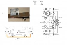
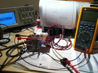
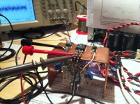
I'm here to break some rules. If you would carefully looked to VSSA pictures, you could notice VAS transistors on the same copper heatsink as ALF. It is on purpose copper and small to make as much as possible stress and fast transfer between both pairs. It is completely stable from 20°C to 75°C as I tested in reality. VAS bias goes from 10 mA to 16 mA, output bias fixed to 100 mA with help of TLVH431 set fixed to 1,565 V.did I read somewhere else they shouldn't even share the same heatsink, but be completely seperated ?
So there's no need for separate on-board VAS heatsinks as you can see.
Main purpose of this compact VSSA amp use is multichannel amp, active speakers, separate horn driver's amp, bookshelf speakers amp, comp amp etc.
LC, thank you for the schematic. Would you like to give a brief comparison of sound quality between VSSA, TSSA and SSA(IGBT)?
Bump.
from your previous post I only thought it sounded like a compromise to have Vas drivers on main heatsink
anyway, I dont think it makes it easier to assemble with drivers on main heatsink
and since the ALF only needs one hole to drill, and thus no tricky allignment, that 'simplicity' would vanish with the drivers
anyway, I dont think it makes it easier to assemble with drivers on main heatsink
and since the ALF only needs one hole to drill, and thus no tricky allignment, that 'simplicity' would vanish with the drivers
The only problem I noticed is thermal bias PTC because of VSA BJT's located on the same heatsink as the outputs. Solution is to use reference adjustable zener for bias spreader or relocation of 2SA/SC to separate heatsinks.
from your previous post I only thought it sounded like a compromise to have Vas drivers on main heatsink
On contrary, for an active speakers amp all heated parts should transfer the heat to outer heatsink, so chamber's inside is heated as little as possible. I extensively tested thermal conditions and with TLVH431 we get simple and reliable solution for perfect thermal stability. As bonus we get also lower THD because Vgg is constant, no matter of the amount of drive signal.
Three screws for transistors on the heatsink are also all fixation PCB needed to be completely stable. I'll definetely do it this way, others can do in a way as suits them most.
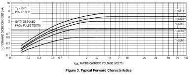
With CRD or another CCS there's no variation at all.
With CRD the problem is Vk-knee voltage from where forward current becomes constant (Vk=2 V for 1 mA diode). It is just to high to be proper for 470 ohm replacement, since there's 0,8 V voltage drop on this resistor.
Attachments
I'll definetely do it this way....
so be it
should I build this, it would be exactly like you will have tested and approved, eventually
you can use a simple CCS. CRDs are integrated jfet CCS.
I know, but still fet based CCS needs much more than 0,8 V to be in a linear current range. Since CRD is integrated j-fet CCS, there's not much difference in behaviour between the two.
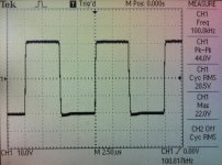
VSSA with CCS (instead 15 k resistors) to inject bias current to the input stage:
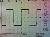
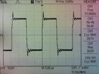
1.pic - 50 kHz squares, 20,1 Vrms/8 ohm, 2,5 Arms
2.pic - the same, only 0,22 uF parallel to 8 ohm load
3.pic & 4.pic - driving 4 ohm speaker with music signal
CCS improvement is noticed. Ringing with 0,22 uF capacitor parallel to load is a little bit smaller and clipping is now fully symmetrical with no artefacts whatsoever, simply cutted-limited with rails.
Attachments
Last edited:
Sorry, I probably overlooked it. Well I always consider basic rule that vertical current has to be at least 10 to 20 times larger than full loading current. In VSSA input bias is 1,8 mA, VAS bias 15 mA and output will be 150 mA on proper heatsink. Now on the test copper heatsink it is set to 100 mA.I asked the question in SSA thread, but got no answer. How do-you decide the current of each stages of an amp.
What do you think about loaded VSSA's squares response?
so be it
should I build this, it would be exactly like you will have tested and approved, eventually
OK, deal.

- Home
- Vendor's Bazaar
- VSSA Lateral MosFet Amplifier