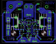
I almost forgot to thank you lineup for this experiment. So even half the VSSA is working good, that means the whole VSSA is good to go guys hehe.Here is HALF the VSSA. It is almost like FETZILLA.
Half the VSSA works well, too.
A little bit more THD(0.007% at 1 Watt), but it behaves well even at higher power output.

TO-3 mosfets are so tempting to have them in one of the amps, could it be VSSA? Let's see ... well done Marc.
Hi LC, these one could do the job : ALF16N16K/ALF16P16K. Here are the datasheet : http://products.semelab-tt.com/pdf/magnatec/ALF16P16K%20ALF16P20K.pdf
Marc
Or this ALF08NP20V5 double n+p channel mosfet in one TO-247-5L case? Just perfect for VSSA. ")
Member
Joined 2009
Paid Member
The following statement is not true :
This amp is a copy cat of Gabor s old amp , so just give credit
where it is due rather than talking of "non similarities" that are
just hollow words since you d be hard pressed if asked to find a single difference.
I see it like this - just because somebody starts a thread doesn't mean they made any clever inventions at all, they just took the initiative to start a discussion. For sure this thread has for me, nothing much original, but it generates some interest and some discussion. I guess some people just like to have their own thread, to do things their way. Carlos the Destroyer being a famous example of that ! - and perhaps true also for Lazy Cat. I agree it could have been made clearer by Lazy Cat.
Look at Pass Labs - you see a lot of old stuff regurgitated and people refer to it as 'Pass design X' when it was somebody else who first showed this topology. F5 is a great example and Nelson also acknowledged that somebody else was selling the same design already before him. There are not so many ways to put things together and they get re-invented over and over. Even the topology that is the subject of this thread was not originally from Gabor and that was said also in that thread.
I hope Gabor continues to develop and build that version, I will be following it too.
Last edited:
I guess some people just like to have their own thread, to do things their way.
If doing the things "your own way" is to make carbon copy of amps and
saying that it s different , yet keeping mum about theses "differences"
and then opening a thread to propose a non mature design (it has been
discussed in many threads) that will be a hassle for beginners , why not ,
since for some it s a raison d etre....
Member
Joined 2009
Paid Member
please, anyone can upload the .asc file?
post 13 is the file I made.
Member
Joined 2009
Paid Member
If doing the things "your own way" is to make carbon copy of amps and
saying that it s different , yet keeping mum about theses "differences"
and then opening a thread to propose a non mature design (it has been
discussed in many threads) that will be a hassle for beginners , why not ,
since for some it s a raison d etre....
Well, the cat is a lazy one afterall
I will concede that it s not for everything he does....Well, the cat is a lazy one afterall
Look at Pass Labs - you see a lot of old stuff regurgitated and people refer to it as 'Pass design X' when it was somebody else who first showed this topology. F5 is a great example and Nelson also acknowledged that somebody else was selling the same design already before him. There are not so many ways to put things together and they get re-invented over and over. Even the topology that is the subject of this thread was not originally from Gabor and that was said also in that thread.
I hope Gabor continues to develop and build that version, I will be following it too.
Hello
Bigun of course I'll do!
I like these design.
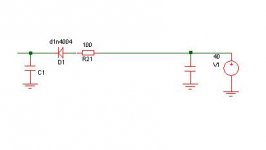
I would advise a small mode which could influence the sound in a positive way.
I did tested with several circuit with or with out and always improved the sound greatly
I would separate the front using a resister and a diode, of course in that case it would be good to ad a pair capacitor to after the diode (front)
I did tested these at my Dalington, Naim clone, and NCC200 clone- always brought a huge sound improvement.
Just a small advise but it would be worth to test it out!
Greetings Gabor
Attachments
Thank you.Well for those folks who like to simulate here's my contribution so far to the Lazy Cat VSSA, a file to play with....
HelloWhich I remember to have first seen on Hafler DH-200 by EB which I am sure someone has seen somewhere before and so on and so forth.
It is very popular because it improve the sound, works.
I wrote I just tested
in a few circuit (made A-B test with and with out) and improve the sound greatly..It would be worth to give a try here to..
Greetings Gabor
Tell us the differences with the "similar schematics" so we can understand where are the innovations....
I have never seen LC as an inventor. Amplifier design is not rocket science, and it is a very old science. Pessimistically, no further invention can be made.
But what differs here is, LC understanding about circuits, especially this topology. His preferences for this topology and the reasons why. The tips how to improve and so on. So the key is in UNDERSTANDING. Without this thread I will have no idea why I should have gone this route myself.
You can design amp, LC can design amp. But LC has an understanding to prefer this topology than the one you just designed. It means, both of you are clearly different.
From my observation, what I can see unique here is:
(1) Preference for the topology (simple, symmetrical, CFB)
(2) BIGBT output stage (tho not my preference)
(3) Complicating the auxiliaries but keeping the stage simple.
(4) Cascaded input as one solution to offset, WITHOUT ever going the servo way.
(5) Benchmarking with high quality commercial amps
(6) Sharing. I know less but I have many that I don't want to share. I don't even want to share my best SSA
Hello
I like these design.Greetings Gabor
Hi Mr. Gabor

Me too, very much. As I was informed you presented this topology to the world, so I would like to express my great admiration to your work and would like to share it further among DIY-ers because it deserves it. Hopefully more and more people will taste this simple amp topology and realize how good it can sound.
My purpose by this thread was to encircle all three types of current feedbacks:
- SSA has DC coupled current feedback, input current injected to the middle of feedback resistor divider where AC is present, constant current source is preferred choice to inject input bias current to achieve correct input-feedback subtraction. Because of thermally dependent Vbe of input pair, SSA topology is the most dependent to thermal drift, great care has to be put to make it stable but as a credit you get flat frequency response from DC
- TSSA has AC coupled current feedback, input current injected to the middle of feedback resistor divider where AC is present, constant current source is preferred choice to inject input bias current to achieve correct input-feedback subtraction. It is an order of magnitude less dependent to thermal drift because feedback ground resistor doesn't conduct DC current, no need for extra thermal stabilization of the input pair
- VSSA has AC coupled current feedback, input current injected to the junction of feedback ground resistor and capacitor where AC is not present, only resistor is sufficient to inject input bias current to achieve correct input-feedback subtraction. Also as with TSSA, no need for extra thermal stabilization of the input pair
Regarding stability and simplicity VSSA is a clear winner, but going more complex by using CCS in input stage, all three converge to very similar results. Most complex of them all, involving all the features, is forthcoming CSA, which is on the test bench at the moment.
- Home
- Vendor's Bazaar
- VSSA Lateral MosFet Amplifier