Each time a fair comparison was made between SMPS and linear supply (even BIG ones) on the same amps, we had found an advantage to SMPS. Cheaper, lighter, less volume, better efficiency
Once again, many "audiophiles" are wrong.
I agree with the observations, but disagree with the conclusion.
It is easy to hear how silent the SMPS is. This silence is measurable, so everyone that can hear will know that the SMPS will measure better (on this parameter). No need measurement tools for that.
The point is to understand what these "audiophiles" hear. Thinking that it is just audiophiles' hallucination is not logical for me.
More common responsible explanation is that the SMPS used is not the good one. This kind of argument is 100% acceptable imo tho I have and still owned expensive SMPS
Chord company in UK are using SMPS in their expensive amps for decades. Nobody complained that SMPS are bad sounding.
Unshielded interconnect cables are used by many audiophiles in an attempt to correct subjective shortcomings of VF amps that always sound like made for pensioners (even when slew rate is high)! I used Kimber unshielded interconnect for years before I found that it is VF amps that are wrong, not the cables. Good CF amp will sound great even with the worst shielded interconnect with 300pF/m capacitance.
LC, you are going to spoil us with your good amp designs. It will be like eating too much sauerkraut with fatty sausages and tons of smoked bacon!
Hi RichardMay I suggest a filter of not less than 40Khz for best results.
As we all know passive filters have a very gentle slope, starting to influence in a wide area around -3 dB point in both directions, so I suggest that this point to be at least 10 times the frequency where we still want the attenuation to be not less than -0,1 dB.
hey Christophe ! check out currnt feedback - voltage feedback -- forum. Good stuff there... design origins and how stuff really works especially current-mode feedback.
-Richard Marsh
Is it a forum or thread here in DIY? Can you please provide a link?
Regards, L.C.
I don't understand anything about SMPS, but I suggest having a look at the DPS line from the recent Audio-Power (designed by forum member AP2).
Those supplies were tested on "The Wire" power amplifier with success, and may be a good alternative.
The DPS-500 and DPS-600 are fully regulated, btw.
You can contact AP2 directly by PM, he is very responsive.
http://www.diyaudio.com/forums/soli...-lme49830-lateral-mosfets-81.html#post2939487
Thank you. I read that thread many times.
")
More common responsible explanation is that the SMPS used is not the good one. This kind of argument is 100% acceptable imo tho I have and still owned expensive SMPS
The intention was purely to show that even cheap, simple and unregulated SMPS like the one used can overcame classic linear PSU and that was clearly proved, not just because of PSRR performance, that at least. SMPS simply brings the amp to higher level of sound quality without any special measures taken. That is also good starting point to go to much more capable SMPS selection and take the most suitable one for VSSA. As Esperado said: "Why bother?" (with heavy and expensive linear PSU).

Agree, that's the most important spec for SMPS, among others too.Long term reliability should be a decisive factor for SMPS brand choice beyond best spec.
Unshielded interconnect cables are used by many audiophiles in an attempt to correct subjective shortcomings of VF amps that always sound like made for pensioners (even when slew rate is high)! I used Kimber unshielded interconnect for years before I found that it is VF amps that are wrong, not the cables.
Yes exactly, that's the fact not recognized by VFA lovers.
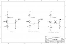
One transistor too much in a feedback path to avoid (fig3.).

Attachments
Yes exactly, that's the fact not recognized by VFA lovers.
One transistor too much in a feedback path to avoid (fig3.).
Ones I already answered to that in other thread. If you are so afraid of "one transistor to much" you can configurate VFA amp in inverting mode, that is, use inverting input as the amp input.
Repeating "one transistor too much in the feedback path" is realy ridiculous. Good reason to use VFA amp in the inverting mode is not "one transistor to much" but less common mode distortion.

Repeating "one transistor too much in the feedback path" is realy ridiculous.
true or not, you should stay to using technical wording, rather than abusing such non tech emotionally loaded words
moderation post
OK, "one transistor too much in the feedback path" it's not techicaly supported.
This always improve VFA amps, as the feedback does not suffer from the distortion of the additional active device in the feedback path: errors are subtracted in a passive way.Ones I already answered to that in other thread. If you are so afraid of "one transistor to much" you can configurate VFA amp in inverting mode, that is, use inverting input as the amp input.
You already made the same mistaken analyze (last time in the non inverting configuration) in the same impolite way. The purpose of CFB is to reduce the number of poles involved in the servo loop. And to deal with the parasitic capacitance at the inverting input (A question of impedance, there).Repeating "one transistor too much in the feedback path" is realy ridiculous. Good reason to use VFA amp in the inverting mode is not "one transistor to much" but less common mode distortion.
We are several to have noticed that CFB amps sounded better than equivalent VFB ones, and it is "ridiculous" to try to convince us of the contrary: your words are light in front of our 'real life' experiences: All the amps i had preferred and chosen (blind) in my recording studios were CFA. Why ?
Just look how behave the bandwidth of a VFA when you change the gain ratio, then do the same with a CFA.
Just look at the point where correction inside the servo loop begin to increase with both of them: Around one octave higher with CFA.
Feel free to propose all the VFA amps of your own design in an other thread, we will compare if you are able to design such a good and simple amp as VSSA. And we will not go polluting your thread with some kind of CFA vs VFA lobbying, as you did... ad nausea.
On the contrary, we will thank-you for your efforts to share your work with the community, as we thanks L.C. for what is a masterpiece.
Last edited:
This always improve VFA amps, as the feedback does not suffer from the distortion of the additional active device in the feedback path: errors are subtracted in a passive way.
You already made the same mistaken analyze (last time in the non inverting configuration) in the same impolite way. The purpose of CFB is to reduce the number of poles involved in the servo loop. And to deal with the parasitic capacitance at the inverting input (A question of impedance, there).
We are several to have noticed that CFB amps sounded better than equivalent VFB ones, and it is "ridiculous" to try to convince us of the contrary: your words are light in front of our 'real life' experiences: All the amps i had preferred and chosen (blind) in my recording studios were CFA. Why ?
Just look how behave the bandwidth of a VFA when you change the gain ratio, then do the same with a CFA.
Just look at the point where correction inside the servo loop begin to increase with both of them: Around one octave higher with CFA.
Feel free to propose all the VFA amps of your own design in an other thread, we will compare if you are able to design such a good and simple amp as VSSA. And we will not go polluting your thread with some kind of CFA vs VFA lobbying, as you did... ad nausea.
On the contrary, we will thank-you for your efforts to share your work with the community, as we thanks L.C. for what is a masterpiece.
The vssa is the closest you get to a beginner cfa AMP
It is stable because of the build up of the input pair.
This is not the case with the vsa.
Many "simple" cfa is not that simple or They are just not stable.
This always improve VFA amps, as the feedback does not suffer from the distortion of the additional active device in the feedback path: errors are subtracted in a passive way.
You already made the same mistaken analyze (last time in the non inverting configuration) in the same impolite way. The purpose of CFB is to reduce the number of poles involved in the servo loop. And to deal with the parasitic capacitance at the inverting input (A question of impedance, there).
We are several to have noticed that CFB amps sounded better than equivalent VFB ones, and it is "ridiculous" to try to convince us of the contrary: your words are light in front of our 'real life' experiences: All the amps i had preferred and chosen (blind) in my recording studios were CFA. Why ?
Just look how behave the bandwidth of a VFA when you change the gain ratio, then do the same with a CFA.
Just look at the point where correction inside the servo loop begin to increase with both of them: Around one octave higher with CFA.
Feel free to propose all the VFA amps of your own design in an other thread, we will compare if you are able to design such a good and simple amp as VSSA. And we will not go polluting your thread with some kind of CFA vs VFA lobbying, as you did... ad nausea.
On the contrary, we will thank-you for your efforts to share your work with the community, as we thanks L.C. for what is a masterpiece.
You say pollution and this is not polite too, this forum is free and should not be privatized by any one. When lazycat called my simulation “your cartoons” is it this polite way to discus technical questions.
I never said that this amp is not good, it is quite good for such simple design, but to say it’s the best ever is a bit funny.
Lazy cat wrote “that's the fact not recognized by VFA lovers”. What facts, because him says that? And call some people VFA lovers is not polite either.
I like technical discussions and if someone says that my design is not what I thought it was, I will not be offended, on the contrary I’ll seek advices and suggestions. I like to learn new things(started to use spice two years ago) even at my age of 68.
Best wishes and hope more openness from CFA club.
Damir
I like to learn new things(started to use spice two years ago) even at my age of 68.
Than at this point please learn what LTP actually is. Please look to my "cartoon slides" from figure 1 to 3 and you'll noticed that LTP is simply emitter follower with additional buffer transistor in the feedback path. No new functionality added, the same subtraction principle preserved as before in figure 1. If that you cannot recognize from this simple 1 to 3 slides explanation, than it's just the phrase expression that you still want to learn something new, but not the real openness.
Than at this point please learn what LTP actually is. Please look to my "cartoon slides" from figure 1 to 3 and you'll noticed that LTP is simply emitter follower with additional buffer transistor in the feedback path. No new functionality added, the same subtraction principle preserved as before in figure 1. If that you cannot recognize from this simple 1 to 3 slides explanation, than it's just the phrase expression that you still want to learn something new, but not the real openness.
Arrogant answer as usual, and you should start to learn.
Sorry to interrupt a technical debate; but it is a bit strange that an SMPS powered CF Amp should sound better than with a Linear Supply, given the amps relatively poor PSRR.
Perhaps, the Linear Supply tested needs to be a lot more stiffer and relatively free of ripple.
These findings are diagramatically opposite to what was reported in the Pass Labs forum with regard to Amp Camp Amp(ACA).
Perhaps, the Linear Supply tested needs to be a lot more stiffer and relatively free of ripple.
These findings are diagramatically opposite to what was reported in the Pass Labs forum with regard to Amp Camp Amp(ACA).
A perfect (and funny) general definition of simulations on my point of view.When lazycat called my simulation “your cartoons”...
Spice simulators save time in calculations (good for lazy people like me), it helps to explore global things in a rough way without wasting solder, but, unless it will be equipped with a virtual listener, i t present the same image of the reality than a cartoon is for real life.
Who said that ?...but to say it’s the best ever is a bit funny
At this level of quality, an other amp can emulate better a given loudspeaker, or will compensate in a better way a given source. But one thing is for sure, the hundred of people witch had immediately subscribed to build one don't needed any simulation to be sure that such a high bandwidth, low distortion, low noise, stability, from a so simple and harmonious design implanted in such a little beautiful board is one of the rare best DIY amp they can buy.
Just looking at the schematic is enough to feel its extreme quality, and I am willing to bet that there will be nobody to prefer an another amplifier in direct comparison, once he has built this one.
Erm, about what dadod said on inverting VFAs...
If we use the inverting input as the signal input then isn't the non inverting input playing as a buffer(cascode) again, now to the input signal rather than the feedback signal? If so, then there is still "one transistor too much" present in the circuit and all previous problems regarding phase/bandwidth remains.
edit: I may be wrong. Please be gentle.
Last edited:
- Home
- Vendor's Bazaar
- VSSA Lateral MosFet Amplifier