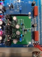
Well i just couldnt leave this circuit alone and instead ended up making a headphone amp out of it. 15v +/- supply V and 300ma bias for the output transistors. I lowered the ccs(?) resistors, the 15k and the 820ohm. They are now 9k and 500 (i should probably go lower?)
The gain is set at 3x with 1000r and 330r
Bias rock stable at 0 to 2ma drift and i havent even thermal coupled the input transistors yet which are bc337 327 that i used them everywhere else
Output transistor bc139 140, output resistors 22ohm. (Should it be lower?) The driver transistors i had initially implemented on the board have been converted to part of a darlington output with the small transistors going to the output via 500ohm resistors.
Sounds very very good so far but i know the values are far from optimal right now. Id greatly appreciate it if someone could sim the circuit at 15v 3x gain so i can go ahead and finish what might be the best headphone amp you could diy