Just boxed the interface in a small plastic project box, added a switch and DC socket, by breaking the USB Bus power at L1, by switch between Ext DC (stabilize DC or Battery) and USB Bus Power to power up the interface, the I2S and DSD output organized by RJ45 socket, I love this little toy so much!!")
Attachments
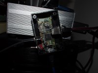
Just boxed the interface in a small plastic project box, added a switch and DC socket, by breaking the USB Bus power at L1, by switch between Ext DC (stabilize DC or Battery) and USB Bus Power to power up the interface, the I2S and DSD output organized by RJ45 socket, I love this little toy so much!!
Very nice, I guess there is not a standard method to interface I2S?
Very nice, I guess there is not a standard method to interface I2S?
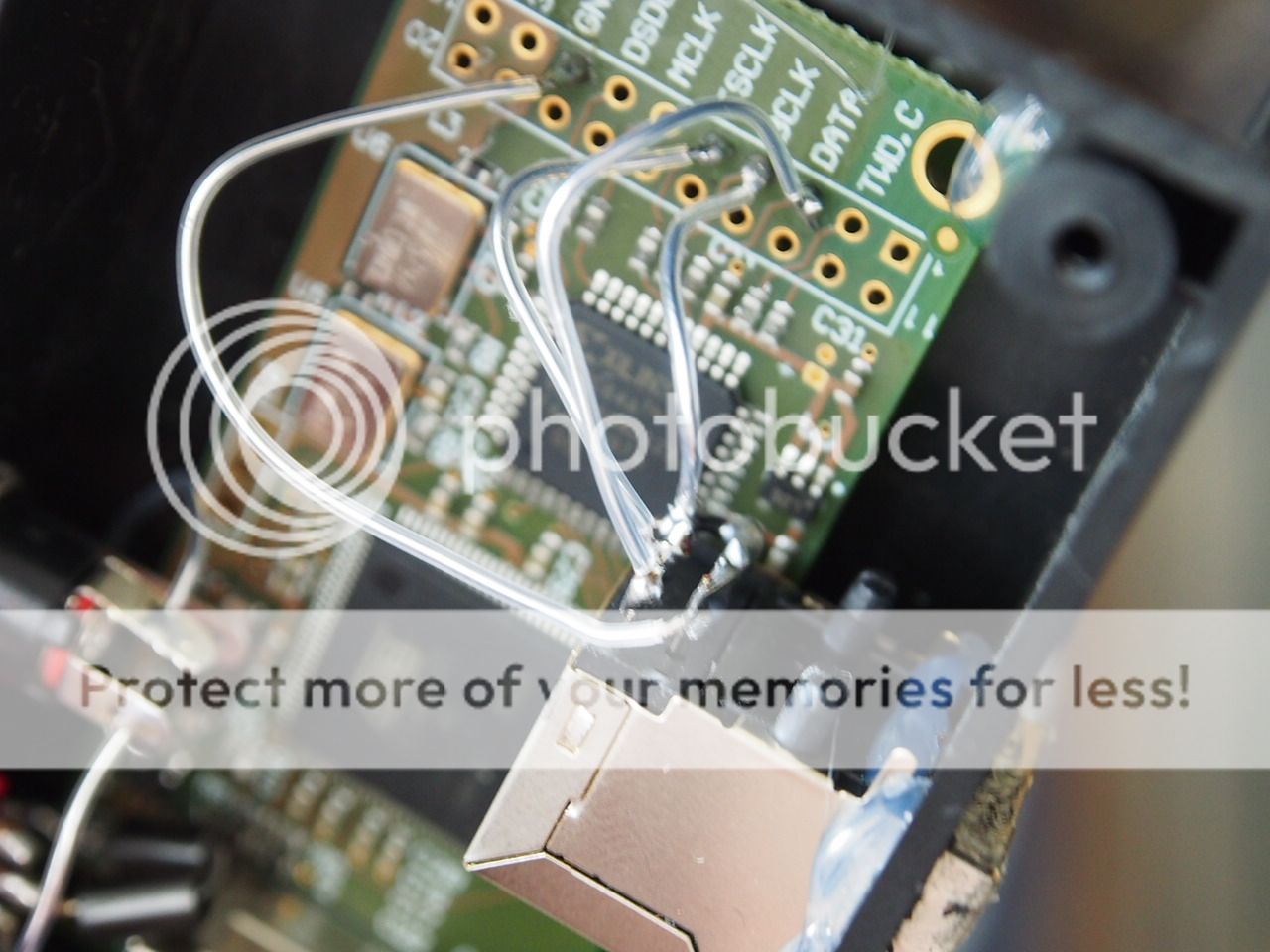
not as far as connector, but as far as connections yes and thats not it, that will be spraying RF all over the place.. its not twisted and there is only a single ground wire, which isnt twisted with any of the signals either. there is a ground connection for each signal connection on the output header for a reason, use them, silver wire will not help here. pair each signal bck, wclk, sdata etc... each one should be paired with its own ground
not as far as connector, but as far as connections yes and thats not it, that will be spraying RF all over the place.. its not twisted and there is only a single ground wire, which isnt twisted with any of the signals either. there is a ground connection for each signal connection on the output header for a reason, use them, silver wire will not help here. pair each signal bck, wclk, sdata etc... each one should be paired with its own ground
too messy to have 4 twisted pairs (8 wires) inside a 1.5"X2.5" box, but after RJ45 all the way twisted and grounded till Buffalo, no dropout for I2S/DSD, acceptable for me.
then use mini coax or ribbon, its only important that there is a ground each signal, what you have there is a radio transmitter. you dont have enough connections there to have it twisted and grounded all the way to the dac, you have a single ground connected
You see single wire of ground but it's grounded to Pin 1, 2, 3, 5, 7 of RJ45, while Pin 4, 6, ,8 carrying Data, BCLK and FSCLK, only last inch not twisted, all pairs grounded.
Last edited:
Agree that in the cable the pairs are all twisted, but you do need to consider continuing those connections from the RJ45 to the PCB. qusp is correct in this case IMO.
Even if you don't twist them, run a gnd wire for each signal wire.
All twisted pair grounded, just use one wire instead of 5 wires, it's meaningless if not grounding them, at the very last inch
Some info here might help - Grounding of Mixes Signal Systems
Other pages on that site also are very informative.
The point is that for signals like i2s the return path should be very close to the signal conductor. I believe there are gnd connections adjacent the FS, BCK and DATA signal terminations on the pcb, my suggestion is to use those, gnd is not simply to provide a common reference potential in this case, the return path of the high freq signal is more complex and when handled poorly will act as a dipole antenna.
what he said^^
additionally they put those ground pads and connections there for a reason, its part of the ethernet spec and ethernet has the advantage of being a differential signal thats buffered and error corrected, i2s does not, it needs all the help it can get to go on a cable
it may seem i'm picking on you, not the case, people look at the photos here to see how things are done, its better they know the correct way to do it. I get emails almost every day asking me about stuff like this, better that its all out there.
if you are using a buffalo dac then iuts probably set to 'best' DPLL, thats a pretty relaxed setting as well
Last edited:
Just my laziness to work in that way in a small box, and want to put it sing ASAP, it's always room for better job beyond working condition.
what he said^^
additionally they put those ground pads and connections there for a reason, its part of the ethernet spec and ethernet has the advantage of being a differential signal thats buffered and error corrected, i2s does not, it needs all the help it can get to go on a cable
it may seem i'm picking on you, not the case, people look at the photos here to see how things are done, its better they know the correct way to do it. I get emails almost every day asking me about stuff like this, better that its all out there.
if you are using a buffalo dac then iuts probably set to 'best' DPLL, thats a pretty relaxed setting as well
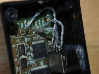
It took me 15 mins to rewire them, as it's all solid core, need a tweezers to hold the wire, as the RJ45 socket is PCB type, quite hard to avoid short of wires.
cool, much better, but it would be a lot easier if you just used Ribbon cable instead of that 50mm of solid core silver...
the point is, when dealing with high frequencies, each signal needs its own return close to it as possible, or it radiates HF noise.... fact, its got nothing to do with just making sure the devices have a ground connection between them. thats why each of the signals in the ethernet cable and each of the signals on the PCB have a return/ground to go with them.
at these high frequencies, the air presents a low impedance (thats why radio signals can travel for billions of KM through air and space), it doesnt really care that much if it has a cable to travel on or not, if it doesnt have a nearby wire to travel on, it'll just go its own way through the air to the nearest point (of its choosing) if need be.
it is not OK to run a single ground, I dont care what Amanero says (if he does indeed say that, that would be strange considering hes given a return per signal on the PCB as there should be) it will work that way, but its not how it should be done.
Last edited:
- Home
- Vendor's Bazaar
- USB to I2S 384Khz - DSD Converter