I have heard that a Chinese tracers users measured 2sk135 is also same as you, but 2sk1058 on this phenomenon.
See the .CUV file for 2SK1058. Condition test as before: N-MOS; Vds Vs Id, Vds=36 V; RB=6k; RC=75
Attachments
Locky,
No Vcc2 on collector of Q1 and 2. I have replaced Q2-4 and still no Vcc2 on collector of q1. I have not replaced q1, as i do not have any. You mentioned Q7 being a possibility, but I do not have a part number and it is a position that is difficult to see. Would you mind giving that to me so I can get it on the way.
No Vcc2 on collector of Q1 and 2. I have replaced Q2-4 and still no Vcc2 on collector of q1. I have not replaced q1, as i do not have any. You mentioned Q7 being a possibility, but I do not have a part number and it is a position that is difficult to see. Would you mind giving that to me so I can get it on the way.
Q2 Q3 collect connect Vcc2
Q1 Q4 collect connect GND

The over current led light, the reason may be:
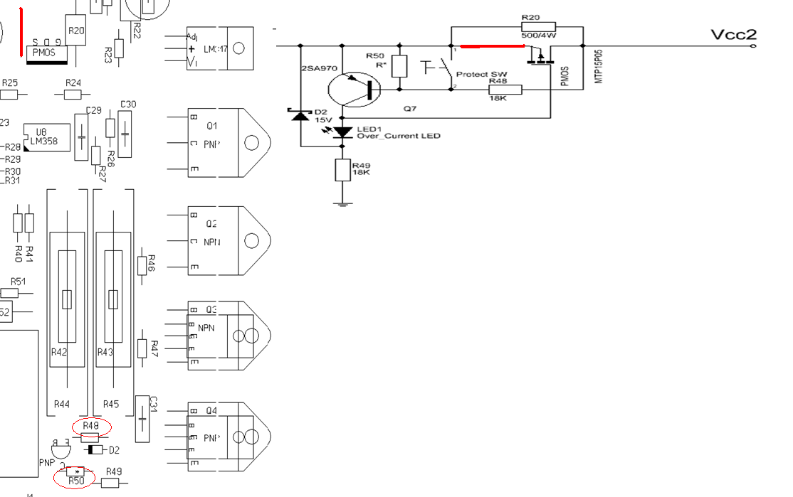
1.Q7(2sa970) C-E is shorted or turned on
2.PMOS G-S is shorted.
if the Vcc2(Q2/Q3collect voltage) is near Vcc, but over-currebt led still light.this mean there are no over current.
Then you can short the portect_sw( it is near the over-currect led,but not install),the sw will short Q7 B-E,If Q7 is ok,then Q7 will cutoff, and the led will not light.
If LED still light, may PMOS G-S is short.
Q1 Q4 collect connect GND
The over current led light, the reason may be:
1.Q7(2sa970) C-E is shorted or turned on
2.PMOS G-S is shorted.
if the Vcc2(Q2/Q3collect voltage) is near Vcc, but over-currebt led still light.this mean there are no over current.
Then you can short the portect_sw( it is near the over-currect led,but not install),the sw will short Q7 B-E,If Q7 is ok,then Q7 will cutoff, and the led will not light.
If LED still light, may PMOS G-S is short.
Attachments
Last edited:
Can you attach it here?
Locky,
I have the the tracer workinf again, but now I am getting very ragged response and cannot even measure in the same way before. Seems unstable. I replaced both the PMos and the Q7 with alternate transistors. I assumed this was not an issue due to the fact that they are not active in the actual measuring process/ Could this be causing my problems? Also, Although I have never cased it up, shold this help performance, providing a sheild from RF or other interferences?
I have the the tracer workinf again, but now I am getting very ragged response and cannot even measure in the same way before. Seems unstable. I replaced both the PMos and the Q7 with alternate transistors. I assumed this was not an issue due to the fact that they are not active in the actual measuring process/ Could this be causing my problems? Also, Although I have never cased it up, shold this help performance, providing a sheild from RF or other interferences?
Q7 and PMOS measurement does not play a role, you can even shorted PMOS D-S. But the protect will disable.
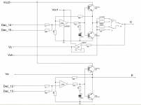
You also can short the Q1 B-E/ Q2 B-E / Q3 B-E /Q4 B-E ,then The LM358 driving the test unit direct. Q1~Q4 not play any role. But you only can measure small signal device.
In this way to see whether the system is stableand.
You also can short the Q1 B-E/ Q2 B-E / Q3 B-E /Q4 B-E ,then The LM358 driving the test unit direct. Q1~Q4 not play any role. But you only can measure small signal device.
In this way to see whether the system is stableand.
I just got one curve tracer.
I am very happy with it....it seems to work wonderfully!
I have one question: Do I need to calibrate the board? I think that once calibration file is sent along with the SW Package.
Does it mean that calibration has been already performed and I don't need to do anything else?
I also was wondering hjow to adjust change scale on the axis it seems to be a little fiddly!
I am so happy look here......")
http://www.diyaudio.com/forums/pass-labs/216616-f6-amplifier-471.html#post3539052
http://www.diyaudio.com/forums/pass-labs/216616-f6-amplifier-471.html#post3539052
I agree. You should also test out the script locky wrote to do the MOSFET characteristic curves (you know Id vs Vds at different Vgs) - I think he's posted it either here or on his yahoo user group.
Unfortunately the curve tracer doesn't seem to work very well with Windows 8 but I'm guessing an update will come out eventually that will fix the problem. I love it so I am keeping my win 7 laptop alive to run it)
Unfortunately the curve tracer doesn't seem to work very well with Windows 8 but I'm guessing an update will come out eventually that will fix the problem. I love it so I am keeping my win 7 laptop alive to run it
)
Last edited:
- Home
- Vendor's Bazaar
- Intelligent Curve Tracer 3.0 release