Could it be for sale?My locky-z is sitting on the shelf collecting dust.
Gerhard

Last edited:
No, as long as I don't have a better solution.
Measurement results like this do not build confidence:
< microchip_dn2470 | Some Vgs vs. ID curves of DN2470 transist… | Flickr >
I doubt the transistor got problems. They are from Mouser or DK and work normally in the application.
Measurement results like this do not build confidence:
< microchip_dn2470 | Some Vgs vs. ID curves of DN2470 transist… | Flickr >
I doubt the transistor got problems. They are from Mouser or DK and work normally in the application.
Last edited:
I've been pondering on the subject of an open sourced project, maybe hosted on github or whatever collaborating platform.
I've been wanting to make such a gizmo for a long time and locky-z's project came fairly close to being what I'd be looking for, however it does have shortcomings and there are things I'd like done a bit differently.
I've had this project on my to-do list long enough and I'm not in a condition to tackle everything all by myself, I can't keep up with it all.
But I have never done any open source stuff and have no idea how to properly do it, with zero experience with the sharing/collaborating platforms.
With enough participants in the project's development, this could become feasible.
One thing would have to be done first: define all of the features and how to implement them.
From my point of view, being entirely a DIY project and not being able to handle any SMT, it would have to be all done through-hole, with off-the-shelf stuff (not obsolete).
And I think something based on some kind of FPGA (cheap ones) would allow further improvements to be made after the hardware has been frozen and made.
Obviously, software wise, open source and multi-platform is a must.
My only usage for such a device would be to match parts, so although tracing curves may be a part of it, the curves themselves aren't that important, the data is what's important and the software feature really required would be to make best use of the data gathered to match sets of parts.
I don't see where a FPGA could help here. It looks more like
a small computer board was a solution. I'm working on a
FFT analyzer built around a BeagleBone Black. Easy bridge
from LAN to flipping bits in real time. Yes, there is a Coolrunner
to collect the misc. logic. Most of the work is getting a Linux
distrib where all the special drivers work together.
Linux on these small computers is a rapidly moving target.
And as far as I was told, the Lucky-Z does not do pulse
measurements. Simply slowly increasing the base drive
will get wrong results because of self-heating. The measurement
should take 100 usec per point, with time for cooling
between the points. Not several seconds.
Do you mean that locky_z [hw && sw] is not a reliable system?Measurement results like this do not build confidence:
< microchip_dn2470 | Some Vgs vs. ID curves of DN2470 transist… | Flickr >
I think there is plenty of potential with FPGAs for this purpose though, and perhaps even the microcontroller itself could be built into that fpga as well.
The key is the hardware flexibility that goes beyond just software.
If open sourced, it should be done in an easy way so someone wanting to build this wouldn't require much beyond the parts to make it, and program that fpga possibly directly on board with only a usb (or whatever) link to a computer, so not only the software/firmware could be sent to the device from a computer, upgraded easily as needed, but the hardware itself could also be upgraded (reconfigured), without any physical changes made to the device.
All done via software from a computer (any platform) via a link, usb preferably, so anyone can do it.
I agree totally about doing the measurements with pulses. That was one of the shortcomings on my list that must be addressed.
When doing power devices, pulsing the measurements is hugely necessary, and not just to minimize the heatsinking required. The measurements would be far more reliable and consistent using pulses for sure, and there would be no need to worry about SOA or whatever thermal issues.
There are real crackerjacks out there with fpgas who could whip something up real good and fast.
I have a little gizmo from china to program eproms and a lot of other similar chips, it's a small footprint, very versatile device and the part count is quite low, because it's all done in fpga.
There must be a good enough and cheap enough fpga out there that could fit the bill, I'm sure of it.
In any case, it must be "open", and by that I don't mean just "open source", it has to be friendly to anyone and as platform agnostic as possible.
locky-z's device has to be used keeping in mind the thermal issues. It's not a matter of reliability really, just that the way it does things isn't as optimal as it could be.
And I find the shortcoming of being windows only to be a big one, and a show stopper for myself.
Plus it's doing curves but not the crunching required with the data to find part matches.
Personally I don't even care about the curves themselves, I want to measure parts and automate the finding of sets among them.
All the above comments on Locky_Z's tracer might be more or less justified, and some of its shortcomings can be dealed with. Using a large mass heatsink with quick-clamps, with a dozen DUTs (or so) clamped on for a minute or so before testing (so that they are all at near same temperature) would yield already better results. I managed to select nice matching pairs for differential input stages for amps without DC offset adjustment that had less than 2mV offset. Which is good enough.
Then for many instances, for example JFET substitution, or VAS or cascode transistor evaluation, then it's rather a matter of comparing values/curves and not a matter of absolute values. Understood that some users might need it for different purposes where absolute values count, but it's perfect for the vintage hifi rebuild and upgrade works that I am into.
Although this curve tracer is not perfect, and as such easy to shoot on, he was at least a person who pushed through an entire hardware + software project. It's for years that I hear folks on various fora talking about wanting to do such project, but so far nobody did. I'll be a front line buyer if anybody puts out the device that they claim about.
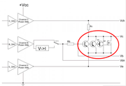
Are the parts in the red circle the DUTs?
An externally hosted image should be here but it was not working when we last tested it.
Attachments

Last edited:
DUT means 'Device Under Test' , i.e. the transistors/FETs being tested.
Several properties of a BJT/(J)FET are influenced by temperature.
For example, measure Vf of a 1N4148 diode with a regular DVM while heating it up between your fingers. In a similar way, the all important Vbe-Ic curve of a BJT is highly sensitive on temperature (hfe much less I learned over the years). Hence, the temperature influence is not neglectable at all when matching is the business.
As such, when pairing is required, the DUTs shall remain at the very same temperature.
This can only be achieved by a large mass of metal that will not be influenced by the few mW (or bigger Watts when high power devices are tested) of heat created when the test current runs through it.
One way of better dealing with this (and being the industry standard as it avoids a fast production line test without the need for manual handling) is using a pulsed test signal (current), but this also has it's limits as mentioned before (yet it provides more accurate results until the DUT is heating up needing longer cooling down intervals).
Locky_z's curve tracer is not using a pulsed test signal but a continuous current signal. Not that evil as such, notably not for simple checking, but the DUT socket is directly on the device's PCB without any form of heatsink (and the test current thus 'corrupts' the test result by heating up the DUT). And thus, one major improvement that any owner could make is to build a heatsink with a wide quick-clamp and a 3-pin Molex socket on a wire (multiple sizes actually to account for 2x1.5mm / 2x2.5mm / 2x 3.5mm lead distance) and a regular TO-3 socket to swap the test leads easily from TO-92/220/3P
Having said all this, the much used Peak Atlas tester is nothing better, and is actually very much more limited in current and voltage, not to mention less PC interface, so Locky_z's tracer is pleasing and serving me very well. Thinking of it, my massive Tektronix 576 has no heat sinking either. ....
I am currently reading the excellent book of Arto Kolinummi (ISBN 9789490929152) who mentions that temperature differences should be kept to less to 0.1 degC while matching discrete JFETs..... well how and whoever will succeed in that? Up to that level, the only solution is to use dual JFET devices.
As far as matching requirements goes, much depends on the rest of the differential circuitry which will allow more or less impairment. Douglas Self quoted less than 10% Hfe difference several times, as the rest will be handled by the quality of the current mirror/sink, emitter degeneration etc. Not to mention that several other parameters like capacitance, bandwidth and Hfe linearity are equally important parameters for circuit performance. So no need to focus on absolute accuracy of a curve tracer and testing temperatures; there is a whole supplementary universe applicable to good transistor selection.
Last edited:
Heat sinking is not the method of choice to do that. The method
of choice is to measure for a microsecond and do that with a 1E-4
duty cycle.
I could not even measure IDSS of my Interfet IF3601 / IF3602 without
pulse measurements. That might be one or two amperes or even more,
and with a few Volts Vds that would kill the FET before the heat
reaches the case.
Alone the fact that you are supposed to control transistor temperature
to 0.1 K begs the question how you enforce that in your application circuit.
Either it is important or not.
And the need to pair transistors is not the solution but the symptom
that the design went wrong somewhere else. You can do that on-chip
with laser trimming the bias resistors, but not on the board.
And before you claim how wonderful these dual transistors are,
take a look at this:
< 8pcs_IF3602 | 8 pairs of Interfet IF3602 JFETs Id vs Vgs | Gerhard Hoffmann | Flickr >
They cost abt. €65 a pop at Mouser's. With 16 or so bought that was
not a cheap measurement.
Last edited:
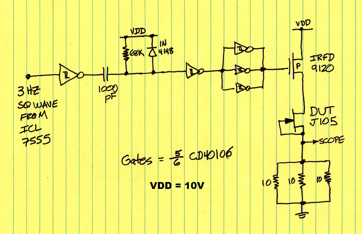
I measured Idss=1.1 amperes on the humble J105, using pulse techniques: (link to diyA post). Duty cycle of measurement pulses was 0.02%: 68us / 333ms. Schematic below.
Hi, do you have locky_z schematic and parts list for his curve tracer? I read that the kit was supplied with schematic... can you share? Thanks in advance.
Pulse measurement technique: any docs to read?
Pulse measurement technique: any docs to read?
I don't think that the "documentation" has much to do with reality.
I would feel less pissed at if I could at least read that user guide.
It's a old google translation of some Chinese pamphlet.
There is not much to that pulse measurement technique. You
bring the DUT into a state where it dissipates nothing. For a BJT
for example, base voltage and/or VCC = 0.
Then you power it up to the operating point that you want to
measure, do your measurement quickly and power it down after that.
Then take a 10 millisecond nap before you measure the next point.
With a BeagleBone Black, that could all be done in software. There
are already the ADCs / DACs on the board or easily connected.
There is Linux on the $50 credit card sized computer. On your
laptop or cell phone, you just open port 5025 on 192.168.178.28
and then you can exchange ASCII strings with your BBB to control
it, just like a modem. For my FFT analyzer, that is about one page of C
to set it up. I patterned the interface after my Agilent 89441A. No ado with
USB drivers or fake chips. Even the compiler/editor is provided locally on
the BBB, as a standard. You just telnet or ssh into that thing.
Wireless, if you want to.
For a view of the entire hardware of my FFT analyzer in statu nascendi
see #2832 of
< DIY Audio Analyzer with AK5397/AK5394A and AK4490 >
cheers, Gerhard
Last edited:
interesting your h/w solution: https://www.diyaudio.com/forums/equipment-and-tools/277808-diy-audio-analyzer-ak5397-ak5394a-ak4490-284.html#post5986973For a view of the entire hardware of my FFT analyzer in statu nascendi
see #2832 of
< DIY Audio Analyzer with AK5397/AK5394A and AK4490 >
Thanks for pulse test info.


Who wants an Intelligent Curve Tracer 3.5_2019 (with software version 3.5 included), please contact me. Thank you
Can we get just the software please?
Software version 3.5 is attached. I didn't include the .ini calibration file, as that's specific to each piece of hardware, but if it's missing there are instructions to re-generate it (or you can email Locky_z with your curve tracer number and have him send you the file).
Attachments
- Home
- Vendor's Bazaar
- Intelligent Curve Tracer 3.0 release