Hi folks,
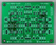
I recently built a preamp with complimentary JFET input pairs and JFET output stages.
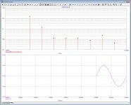
It produces very low distortion and renders an elegant and sophisticated sound typical of JFETs.
The project started with MicroCap simulation and was perfected with elaborate tweaking.
View attachment 63308-C sch.pdf
PCB layout was done with Eagle 11.
View attachment 63308-C pcb.pdf
Item will soon be available.
Regards,
US Audio Circuits
I recently built a preamp with complimentary JFET input pairs and JFET output stages.
It produces very low distortion and renders an elegant and sophisticated sound typical of JFETs.
The project started with MicroCap simulation and was perfected with elaborate tweaking.
An externally hosted image should be here but it was not working when we last tested it.
View attachment 63308-C sch.pdf
PCB layout was done with Eagle 11.
An externally hosted image should be here but it was not working when we last tested it.
View attachment 63308-C pcb.pdf
Item will soon be available.
Regards,
US Audio Circuits
Hi folks,
I recently built a preamp with complimentary JFET input pairs and JFET output stages.
It produces very low distortion and renders an elegant and sophisticated sound typical of JFETs.
The project started with MicroCap simulation and was perfected with elaborate tweaking.
Regards,
US Audio Circuits
Can you show us some sim results please?
jan didden
Pure coincidence, no doubt !!
I hope Erno will forgive me in this particular case for uploading his schematics, which was published at his website.
Patrick
I've never seen this design, and I arrived at something very, very similar quite independently a very long time ago. I would proceed cautiously with this allegation. Everything I see here is prior art, and the proposed design actually differs in several key respects - I'll leave that to you to figure out.
I have built I/V and LineAmplifier full cascoded versions with small changes to the circuits allowing of extra cascode biasings in case proper devices are not found. So far I was able to startup I/V in passive mode. Because of the reasons above I will not post a detailed circuits but can post schematics without a values, and simulation results if anyone is interested.
The board contains 2 channels with power supply.
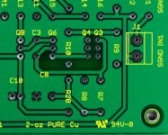
Copper thickness is 2-oz (70µm) for excellent signal & current conduction.
This is usually thick for a preamp. Your PC video card is 0.5-oz (17.5µm).
White silkscreen for component side and yellow for bottom.


Component side.......... Solder side with yellow silkscreen
Regards,
US Audio Circuits
Copper thickness is 2-oz (70µm) for excellent signal & current conduction.
This is usually thick for a preamp. Your PC video card is 0.5-oz (17.5µm).
White silkscreen for component side and yellow for bottom.


Component side.......... Solder side with yellow silkscreen
Regards,
US Audio Circuits
This design was invented by Erno Borbely in one of the Audio Amateur or Glass Audio issues few years back. It was not permitted for commercial use. But Erno sometimes sells his design to other companies. Anyway most likely this design is not patented by him, but even in such case is nice to at least include information about original inventor. :/
- Status
- This old topic is closed. If you want to reopen this topic, contact a moderator using the "Report Post" button.
- Home
- Vendor's Bazaar
- FS: PreAmp with Complimentary JFET Diff input & JFET ouput
 I'm moving this over to Vendors' since it is clearly a commercial offering.