MY DESIGNER。
Reference IR official circuits and wiring.
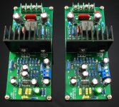
IRAUDAMP7S-150
By IRS2092 + IRFI 4019 MOSFET FOR audio only.
Full-line design,
Supply voltage range of + - 45V ---- + - 60V
+-55V 150W 8R, 300W 4R.
EMAIL : 646216200@qq.com

Reference IR official circuits and wiring.
IRAUDAMP7S-150
By IRS2092 + IRFI 4019 MOSFET FOR audio only.
Full-line design,
Supply voltage range of + - 45V ---- + - 60V
+-55V 150W 8R, 300W 4R.
EMAIL : 646216200@qq.com
Attachments
Last edited by a moderator:
MY DESIGNER。
By IRS2092 + IRFI 4019 MOSFET FOR audio only.
Interesting, that combination is the same as my 2092 design.
The 4019 has low gate capacitance and I use four of them in my design.
I tried the reference design but had a number of issues with it.
To start with the 2092 just kept resetting.
1/ I had to decouple the mosfets very closely.
2/ The VCC rail had glitches on it and needed extra decoupling.
3/ My 12 volt regulator didnt like the 2092 pulsing current and needed extra decoupling.
4/ I kept getting huge thumps through my speaker on power down. The startup capacitor was too big in the ref design and I used 1uf.
I blew up 7 2092's trying to get it working as unplugging the 2092 then plugging it back in with charge on the capacitors blew it up.
Finally got there now with a good solid design.
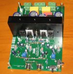
I think to the IC does not require separate external power supply VCC 12V regulated DC power supply.
In the IR official design is the use of 1N4744, resistor divider-type power supply.
This has several advantages, resistance and voltage RC after forming a capacitor filter.
But also in the partial pressure of three of the input voltage terminal, there is a 1K 1W power resistor string can explain the problem.
I think to the IC does not require separate external power supply VCC 12V regulated DC power supply.
.
I used a dropper resistor from 45 volts and a 78L12 voltage regulator.
This version of line parts are used, but did not use many of the posts with digital amplifier chip components.
This is because the line components reliability, power consumption than the post-chip components are to be good.
Quote sheet resistance are basically carbon, 5% error, temperature drift great. The line of metal film resistors 1% tolerance, low temperature drift of 50
PPM.
Post-chip capacitors are made of ceramic such composition, temperature drift large and very small pressure, not suitable for high-power machines.
Line oscillator form with CBB to do, almost no temperature drift and error, at very low or very high temperatures can also be good work.
Here is mine...
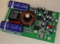
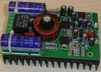
Single channel, IRS2092S driven class D amp, output power up to 600W (with other MOS-FET's and caps) the shown one has 300W. the main application is multi-channel amplifiers. it only requires the main differential supply voltage, and has some ingenious power management scheme to save power as much as possible. Dead-time is set to min. 25ns, and the pk-pk overshoot is about 2V only, due to the tight layout.
I've made them for a friend who integrates them in some amps which he build. Soon i will have a batch for sale on my site too.
Attachments
Single channel, IRS2092S driven class D amp, output power up to 600W (with other MOS-FET's and caps) the shown one has 300W. the main application is multi-channel amplifiers. it only requires the main differential supply voltage, and has some ingenious power management scheme to save power as much as possible. Dead-time is set to min. 25ns, and the pk-pk overshoot is about 2V only, due to the tight layout.
I've made them for a friend who integrates them in some amps which he build. Soon i will have a batch for sale on my site too.
Hi Cristi,
Excellent boards! There are really nice SMPS and amp modules in your web site!
By the way are you using a single power IC (for eg. FSFR series from Fairchild) for HB resonant mode smps' or your are making your own control via pwm cont./driver/mosfet combination?
Congratulations! and happy new year.
Thank you for your kindness,
I have been playing with most of the existing LLC IC's, both integrated (FSFR1700-2100) and controllers, and for the power supplies which i made for audio i have used exclusively L6599 till now due to design flexibility. with other ic's, I have made some power supplies in range of hundreds of watts to several KW levels, for target applications, not audio (3.6KW battery charger for EV) using UCC25600 and NCP1395. both this ic's allows HB or FB configuration, and DT can be adjusted conveniently.
With FSFR2100 i will have a SMPS for audio in short time from now, which will have something special than the available ones.
Thanks for your nice explanation. I am dealing with fuel cells as a chemist and at the end of the production process i need to create my own power compansating unit. Hence in near future i am planing to use FSFR2100 for low power compansation unit (for a laboratory show) after a boost converter. It seems we are both really interested with green energy(wind mill, solar cell,fuel cell etc. are alternative electricity sources for future EVs) but i am mostly in the scientific part of the work
. Anyway, thanks again. Best wishes,
Ferda
I bet your final test will be, driving home in EV with your design that you do, and will do
Oh and happy new year to you too!
First of all sorry for the off topic!
Hi Luka,
Happy new year and it is nice to see you again! You are right! That is the plan but, need time! Unfortunately, providing developments in basic science not very quick and easy ( If you have access try this; Azole substituted polyphosphazenes as nonhumidified proton conducting membranes - Journal of Materials Chemistry (RSC Publishing)). However once you did it takes its place in daily use very quickly! Therefore, I do not mind designing a robust inverter/converter for that purpose! Because one of the experts here can do it or it is possible to order a custom designed one from a commercial source. However, for basic tests and show in a laboratory (for an electronic DIYer chemist) it is better to build your own device (Is it?).
Best wishes,
Ferda
omfg
Hi guys,
I need your help. I am trying to build a class-D amp with a IRS2092. I fully rebuild this design: http://www.irf.com/product-info/datasheets/data/irs2092.pdf
I used +-30V for +-B (labratory supply) and +12V with another labratory supply and the - of that supply connected to -B so VCC will be -23V referenced to ground (like in the pdf). With only the VCC turned on, the chip will need 200mA and gets really REALLY hot and that can't be a good thing.
When turning on the +B and -B without a load (speaker), the chip will first blow itsself up and then the outputcapacitor in the LPF (50uH and 1uF). When i try to measure the signals going to the gate of the fet, i don't see a PWM signal. The supply itsself will reach its current limit (3A) and this is WITHOUT laod, this even happens without the fets (although they are necessairy to recieve a feedback)
Anyone knows what i am doing wrong?
Hi guys,
I need your help. I am trying to build a class-D amp with a IRS2092. I fully rebuild this design: http://www.irf.com/product-info/datasheets/data/irs2092.pdf
I used +-30V for +-B (labratory supply) and +12V with another labratory supply and the - of that supply connected to -B so VCC will be -23V referenced to ground (like in the pdf). With only the VCC turned on, the chip will need 200mA and gets really REALLY hot and that can't be a good thing
.When turning on the +B and -B without a load (speaker), the chip will first blow itsself up and then the outputcapacitor in the LPF (50uH and 1uF). When i try to measure the signals going to the gate of the fet, i don't see a PWM signal. The supply itsself will reach its current limit (3A) and this is WITHOUT laod, this even happens without the fets (although they are necessairy to recieve a feedback)
Anyone knows what i am doing wrong?
update:
I read something about the IRS2092 being a bitch with decoupling so i added some big capacitors. The all are 680uF.
Locations:
+B to ground
-B to ground
+B to -B
VCC to -B
The VSS will still reviece about 300mA and sometimes even the currentlimit (1.5A). And this is without turning on the -B, +B and load. With laod i mean, ofcourse, the speaker. I still have no outputsignal at the fet gates, nor on Vs.
Im out of ideas
update:
The VSS will still reviece about 300mA and sometimes even the currentlimit (1.5A). And this is without turning on the -B, +B and load. With laod i mean, ofcourse, the speaker. I still have no outputsignal at the fet gates, nor on Vs.
Im out of ideas
Which MOSFETs are you using ?
It definitely works with irfb4019's.
I have 4 on my setup.
Does the csd pin go up and down ? this would indicate something is wrong with the power supply or the mosfets.
update:
I read something about the IRS2092 being a bitch with decoupling so i added some big capacitors. The all are 680uF.
Locations:
+B to ground
-B to ground
+B to -B
VCC to -B
The VSS will still reviece about 300mA and sometimes even the currentlimit (1.5A). And this is without turning on the -B, +B and load. With laod i mean, ofcourse, the speaker. I still have no outputsignal at the fet gates, nor on Vs.
Im out of ideas
Right, Are you sure you soldered the IC in correct way? Check the electrolytic caps polarities and be sure there is not short circuit. I also recommend to clean the board from solder paste with isoporpyl alcohol or thinner. After all these, first turn on the aux power to see whether you are getting the reference voltage from the IC and check its temperature as well (without output mosfets).
Best wishes,
- Home
- Vendor's Bazaar
- LJM Audio