Goodmorningyou really need this PDF, other one is totaly useless
http://www.irf.com/technical-info/appnotes/an-1138.pdf
here you will find some values... I have found that because I have such fets and all, I have diffrent values, so expect to have diffrent freq., so don't go crazy with values
You set is by resistor an 2 capacitors
What fets are you using?
maybe you should remove those big capacitors for now, since those provide the current to do that
show me schematic that you have now, I won't check the pcb if everything is connected where it should be though
")
Thanks for the document. I have some news:
The short is gone now, none of the fets (IRFB4019) are breaking now.
I replaced the diode connected to the high side output to an ultrafast switching diode.. the one i usd was way too slow. Same goes for the low side and high side capacitors. They are now high speed MKT capacitors.
I also set the PWM frequency to ~300kHz.
So now nothing is breaking, but it isn't working either. Any suggestions?
And again: thanks for all the help
edit: Since none of the fets are open, we dont have feedback. Signal on the -IN is the same as the one generated by our functiongenerator and om COMP we have a signal of 1V (looks like DC)
Last edited:
they all need to be ultrafast switching diode, at least fast switching diode, since this is fast switching circuit by nature
So what does it do now? myself, I would already had connected scope, and check before LC if there is anything going on at all, I would check all the voltages that I asked before
maybe start posting scope pictures.
There really is nothing to it, IC will start switching if conditions are met
So what does it do now? myself, I would already had connected scope, and check before LC if there is anything going on at all, I would check all the voltages that I asked before
maybe start posting scope pictures.
There really is nothing to it, IC will start switching if conditions are met
voltage between pin 10 and 12 : 12V
voltage between pin 1 and 2 : 5.6V
voltage between pin 2 and 6 : -5.6V
voltage between pin 13 and 15 : 8.5V
voltage between pin 5 and 6 : 11V
voltage between pin 8 and 12 : 4V
voltage between pin 7 and 10 : 8.8V
So its something with the security?
Last edited:
ok first of all, instead of 8 and 12 I wanted to know 8 and 10, 10 being negative supply
pin7 should be 5.1v, not 8.8v, that up with this, is it correct?
Also what is voltage between 9 and 10
15 is a bit low, that could be the problem, since I think I had problems like this, when I didn't supply enough for that driver
If you can, you can just tell me all the pin voltages, compared with ground, so black lead to gnd, and then probe every pin of irs
and post here... then I can check compared to my
Well, this chip has a busted zener, so it won't work anymore. This is probably because the fets and the chip were getting hot again (and i have absolutely NO clue how).from what does it get how??
I mean your fets as you say don't open, supply voltages are below internal zener, so that can't be the reason,... what else could it be
Are this ic that cheap for you? where do you buy them and for how much?
Edit: And i'm too lazy to get another power supply for the 5V
This IC is about 5EUR for me, but the university is paying so i don't care haha
ok lol, still 5€ is better then 9€ for meWell, this chip has a busted zener, so it won't work anymore. This is probably because the fets and the chip were getting hot again (and i have absolutely NO clue how).
Edit: And i'm too lazy to get another power supply for the 5V
This IC is about 5EUR for me, but the university is paying so i don't care haha
Are you doing this as a project or what?
I mean I didn't kill not one, this is my first and still works, and by still works, I wasn't able to kill it
But I did do a good pcb, at least I would like to believe so
I mean I didn't kill not one, this is my first and still works, and by still works, I wasn't able to kill it
I killed 7 2092's before I got one working.
Its easy to kill them poking about with scope probes while it is switched on.
My other mistake was to unplug the 2092 from its socket while power supply capacitors were still charged up.
Even now I am still learning about the 2092. I found it cut out at high power and this turned out to be the inductor was saturating and shorting out the mosfets. Replaced the 10 amp inductor with a 16 amp one and it was then fine.
The 2092 is very touchy about decoupling across the mosfet supplies and also around the 2092. The VCC supply takes high frequency pulses so need a lot of care around the regulator and the 2092.
Had problems with turn off thumps and a 1uf on the CSD pin sorted that.
Also found 22uf on the VAA and VSS supplies helped.
A long learning curve.
Yes, but all those things you learn over the years, at least I did
For unknown reason, at first it didn't work for me either, but after I've seen your, I had to try again and that time it worked, but distorted... which was soon fixed
About inductor I don't know, I clip the amp with +/-50v or so with no problems
For unknown reason, at first it didn't work for me either, but after I've seen your, I had to try again and that time it worked, but distorted... which was soon fixed
About inductor I don't know, I clip the amp with +/-50v or so with no problems

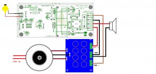
I like to use IRS2092 plus IRFI4019, 4020 amplifier.
This is the design of the power amplifier AUDAMP7 reference, they can reach 125 200 W power 8ohms
.
250-300 W 4 ohms
.
This is the power of the household relatively appropriate, has the smallest distortion (good effect)
I don't think too DuoRen inside the home use square of radio.
More power and voltage MOSFET and not in ascension.
Also in relation to the inductor capacity. This requires 1 MM copper wire many root in parallel, many people ignore this.
We must use load, to test whether the inductance of the cores can bear.
More power to bring the larger current, make ordinary PCB can't reliable and stable.
Need more thick copper PCB line.
All of these will greatly enhance the production cost, because they will use the non-standard equipment.
With great power transformer and will be very expensive. Finish all of these, and perhaps we only used it 1/10 of the power.
Last edited:
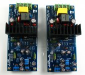
Ljm_ljm, I would like to purchase a pair of your new REV3 L15D's. Can you recommend an online vendor that will have them?
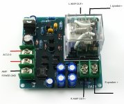
L15D Digital Audio amplifier board IRS2092 IRFI4019H | eBay
Now the version is going to change for REV3.
It has a smaller distortion, better performance.
L15D recommend using DC +-50 V power supply.
Can output the 125 W 8 ohms, the power of the 250 W 4 ohm power.
+-55 V (150 W 8 R) (300W 4R)
Attachments
- Home
- Vendor's Bazaar
- LJM Audio