Just another L7.
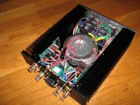
This is my ljm-L7 power amplifier:
- 2 ljm-L7 DIY kits;
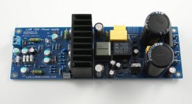
- 2 ljm 63V 2200uF Supply board kits;
- 1 stereo speaker protection board;
- toroidal transformer INDEL 300VA, 2x28 Vac;
- DIY aluminum case from ebay.
No problem, it sounds good")
Many thanks to LJM.
This is my ljm-L7 power amplifier:
- 2 ljm-L7 DIY kits;
- 2 ljm 63V 2200uF Supply board kits;
- 1 stereo speaker protection board;
- toroidal transformer INDEL 300VA, 2x28 Vac;
- DIY aluminum case from ebay.
No problem, it sounds good
Many thanks to LJM.
Attachments
hi ljm,
i ordered the l15d kit. it sounds terrific. it came from zoe-tzang with 33uf oscons and 270ohm resistor in place of the 470r. i thought it might be a mistake, so i put in 22uf and changed resistor to 470r. so i just now see that you recommend 33uf. if i try 33uf oscons, should i change back to 270r? thank you. these amps are amazing.
regards,
freeman
270 OHM ,25V33UF OSCON ,No problem.
Resistance to the PWM frequency.
It is recommended to use 270 ohm + - 50 v, about 40 v + - use 300 ohms
Last edited:
270 OHM ,25V33UF OSCON ,No problem.
Resistance to the PWM frequency.
It is recommended to use 270 ohm + - 50 v, about 40 v + - use 300 ohms
thanks ljm,
i've experimented with different caps and resistor values. i also tried different brands of caps, but my favorite is the originals from zoe-tsang (33uf and 270r). the l15d is currently my favorite amp. i'm using 6 abletec +/- 53v smps in a tri-amped setup. sound is terrific. i prefer very detailed sound that i get with the l15d. thank you.
I want to use two of these boards normally in stereo but also in bridge mode. For normal use, one of the boards (called it Board 'B') will be installed with inputs and outputs reversed (to maintain correct phase).
If I want to bridge is it simply a matter of connecting the mono signal to both boards and then connecting the speaker outputs positive to the + output of board A and the negative speaker output to the + out of board 'B'?
I am planning on using an Ardunio /w relays to control the switching.
If I want to bridge is it simply a matter of connecting the mono signal to both boards and then connecting the speaker outputs positive to the + output of board A and the negative speaker output to the + out of board 'B'?
I am planning on using an Ardunio /w relays to control the switching.
LJM, is there something to watch out for with the 2sc1815 transistors? My kit had one missing. Can I just use the regular 2SC1815 on your board??
Thanks.
No problem.
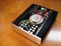
This is my ljm-L7 power amplifier:
- 2 ljm-L7 DIY kits;
- 2 ljm 63V 2200uF Supply board kits;
- 1 stereo speaker protection board;
- toroidal transformer INDEL 300VA, 2x28 Vac;
- DIY aluminum case from ebay.
No problem, it sounds good
Many thanks to LJM.
If there is only one group of voltage, AC28-0-28 I think a power board would be more appropriate.
If a group of voltage and the connecting two power panel, earth may form interference noise.
If there is only one group of voltage, AC28-0-28 I think a power board would be more appropriate.
If a group of voltage and the connecting two power panel, earth may form interference noise.
Use two power boards with a single AC may be an unusual choice and with little or no benefit.
I started to make two independent channels, this is why I bought two power boards. In the end I tried to use two power boards equally, with the uncertainty of producing noise.
Really there is no audible noise
I want to use two of these boards normally in stereo but also in bridge mode. For normal use, one of the boards (called it Board 'B') will be installed with inputs and outputs reversed (to maintain correct phase).
If I want to bridge is it simply a matter of connecting the mono signal to both boards and then connecting the speaker outputs positive to the + output of board A and the negative speaker output to the + out of board 'B'?
I am planning on using an Ardunio /w relays to control the switching.
It won't work that way.
You need to use an external phase inverter circuit for board B input.
It is a simple opamp based circuit, can be fed from the 5V6 zeners on the board.
thanks ljm,
i've experimented with different caps and resistor values. i also tried different brands of caps, but my favorite is the originals from zoe-tsang (33uf and 270r). the l15d is currently my favorite amp. i'm using 6 abletec +/- 53v smps in a tri-amped setup. sound is terrific. i prefer very detailed sound that i get with the l15d. thank you.
Don't mention it.
I as long as free Will for components, or numerical test, and then improve.
The same circuit, but the actual effect of the finished product often vary widely.
This is different elements, even the position of the element.
Anyone have a link to a L15-Pro assembled with the oscon cap version?
I'd L15D-Pro for the extra speaker protection and also would like the version with the new oscon caps changes by ljm.
I temporarily does not provide L15D - PRO OSCON capacitance version.
Because the capacitance is not cheap, HA HA.
You may want to consider L15D - POWER ,But 2 stereo need 2 *transformer. AC 36-0-36
Attachments
Hi r100,
I forgot to answer regarding the power supply. Yes, most of the protection boards need a separate (12V) AC supply. It can be a separate winding of a transformer. If you would use the DC voltage after a capacitor bank the stored energy of the capacitors will take a while to unload so the relais will switch off to late and you might hear some noise from the speakers when you switch off the amplifier.
Just to be clear... One can use one transformer with the following windings, 36V AC & 12V AC? Use 36V to power supply/amp and on the same transformer use the 12V AC for the speaker protection unit?
Hi Anton,
very interesting, there are some other IRS2092 based amps I have not seen before. For example this L20D is a version that has new capacitors installed:
L20D 200 250W 2 8ohm Stereo Class D IRAUDAMP7 IRS2092 IRFI4020 Completed Board | eBay
and here is a amp called L30D:
L30D 300 850W Mono Digital Amplifier IRS2092 IRFB4227 IRAUDAMP9 | eBay
It should be an easy way to build an amp with the boards you have found, because you need only to connect a transformer and speaker protection is also included.
Regarding cabling I would prefer a longer power cable. But if you use for example 1,5 or 2,5 mm wires for the loudspeakers I don't think you would have problems. But this is just my opinion and I don't want to start a discussion about the influence and sound of cables.
A Transformer with 2 X 40V should be fine, and will give about 56V on the capacitors. 300 or 400 Watt Transformers should be enough but if space and wight is no problem you can use 600W Transformers.
By the way I have also the L26ROY's at home and will build 3 way loudspeakers controlled by Class D amplifiers.
I wonder if the 850W module could get by using 86V. I have am old amp that could be repurposed.
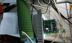
It is a SMD version L15D model.
The same structure.
By IRS2092S IRFI4019H composition.
It is a MINI version, the position of the element is similar to IRAUDAMP7S.
It suggested that + - 40 v to + 60 v voltage
Recommend + - 50 v voltage.
Can obtain 125 8 r w, 125 w 4 the output power.
Details about the test and can reference IRAUDAMP7S data.
Is that output power correct? I thought it was 125W 8R, 250W 4R?
Currently there are no L50 amplifier boards for sale on Ebay (US) or AliExpress... I find this a little strange.
LJM do you know why?
I sold many L50, but I don't know what's international purchasing businessmen's web site.
I think should be able to find on the Internet.
LME49810 AMP BY LJM
ME 49810 is the United States, the national semiconductor's latest flagship amplifier chip.
Due to the common IC power amplifier is a single integrated circuit chip.
In other words, audio amplifier input stage amplifier stage, output stage, are all on the same chip.
Power output stage will produce larger quantity of heat, and the heat will feedback to the same chip small signal input stage, and the signal amplifier stage at the corresponding level.
The mechanism of distortion is called thermal distortion. This in SELF book also have detailed records, and testing.
So NS national semiconductor in order to solve this problem, in later products launched in 49810, the LME LM49830 series power amplifier IC.
49810 is the small signal amplifier stage, the design of the separation of the current output stage,
This has greatly increased the power amplifier ?
Attachments
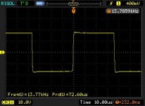
I use a 1000 w 8 ohm resistance.
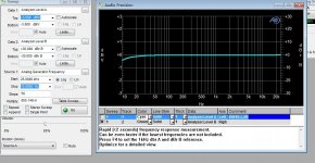
audio Precision 2 test:
Frequency response: 20 HZ - 25 k HZ - 0.1 DB
10 hz to 0.4 DB
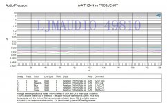
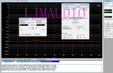
THD+N= 20W RMS 0.0015%
15W RMS 0.002%
THD+N = 40W RMS 25.5VP 0.002% 20HZ-20KHZ
audio Precision 2 test:
Frequency response: 20 HZ - 25 k HZ - 0.1 DB
10 hz to 0.4 DB
THD+N= 20W RMS 0.0015%
15W RMS 0.002%
THD+N = 40W RMS 25.5VP 0.002% 20HZ-20KHZ
Attachments
- Home
- Vendor's Bazaar
- LJM Audio