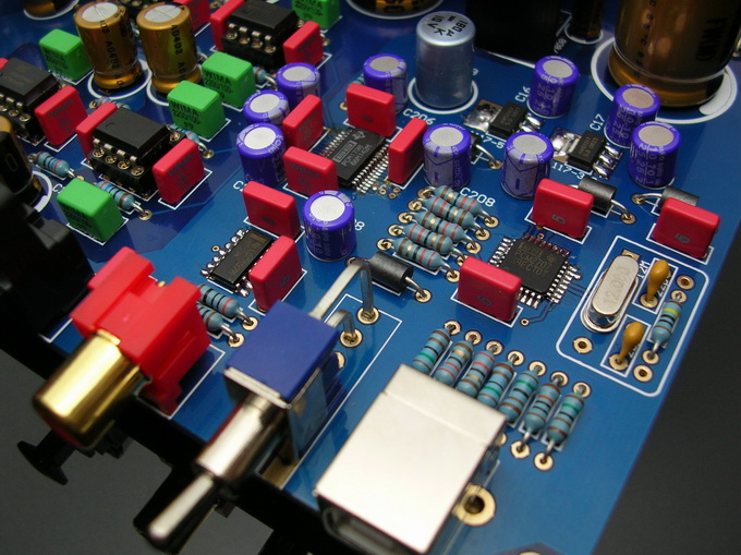
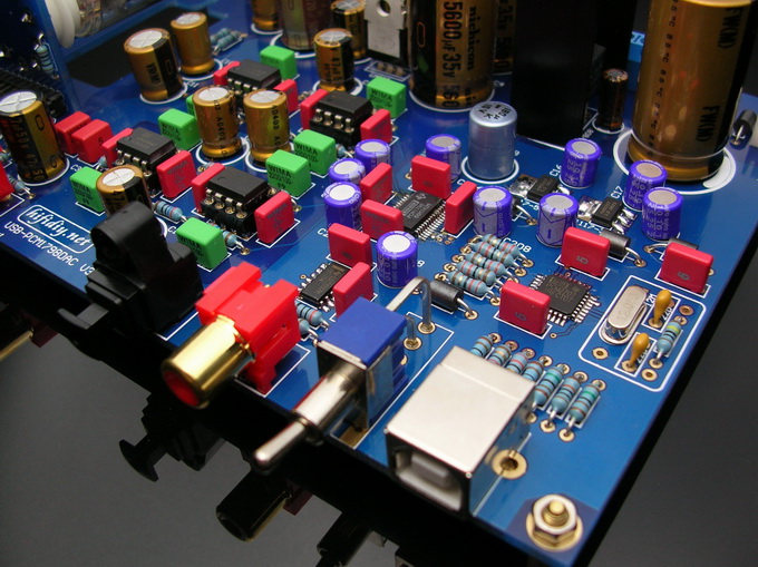
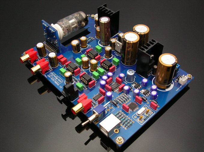
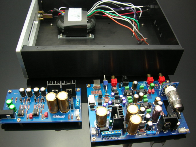
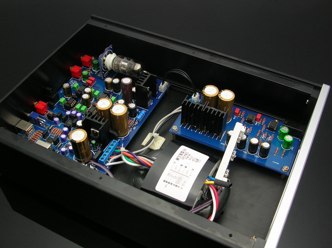
We DIY Working Group£¬design a USB tube DAC¡£The main channel is usb interface£¬direct input to PCM2707£¬and then directly through the I2S input directly PCM1798£¬then through four separate operational amplifier IC for I / V conversion£¬Tube output buffer stage output£¬buffer to adjust the sound level£¬also can use jumper to selected to determine whether the tube buffer stage£¬specially design multi-channel power£¬can be for headphone amplifier£¬the entire line Simple and clear£¬Pipeline Design¡£
The DAC also psimultaneously rovides two-way digital signal output: Coax and Fiber
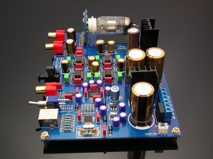
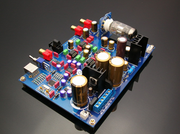
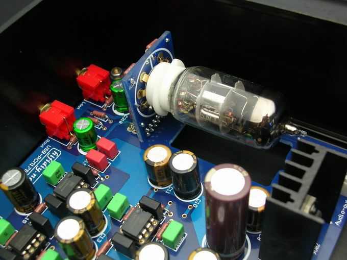
In addition£¬tube and power supply to buy their own£¬but We are presented with two tubes PCB package

The DAC also psimultaneously rovides two-way digital signal output: Coax and Fiber
In addition£¬tube and power supply to buy their own£¬but We are presented with two tubes PCB package
can use our power supply
1)15V 0 15V 60V--------25W
2)15V 0 15V-------------15W(for headphone amplifier)
3)8V 0----------------- 16W
110V--220Vac
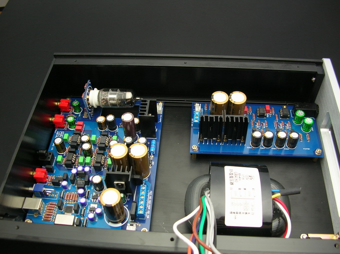
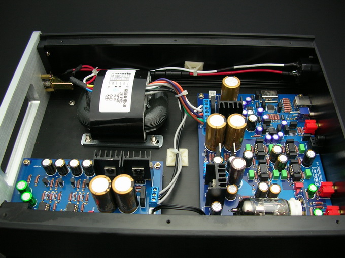
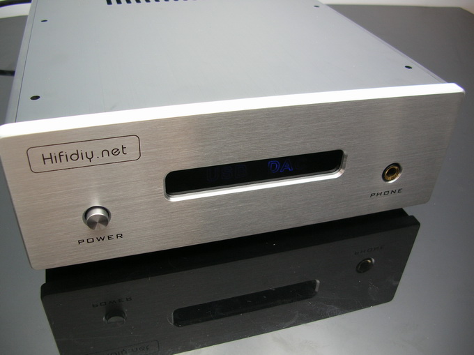
In addition£¬We also designed a shell£¬headphone amplifier£¬then the power supply, headphone amplifier, usb tube DAC, assembled together£¬you can see£º
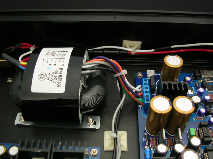
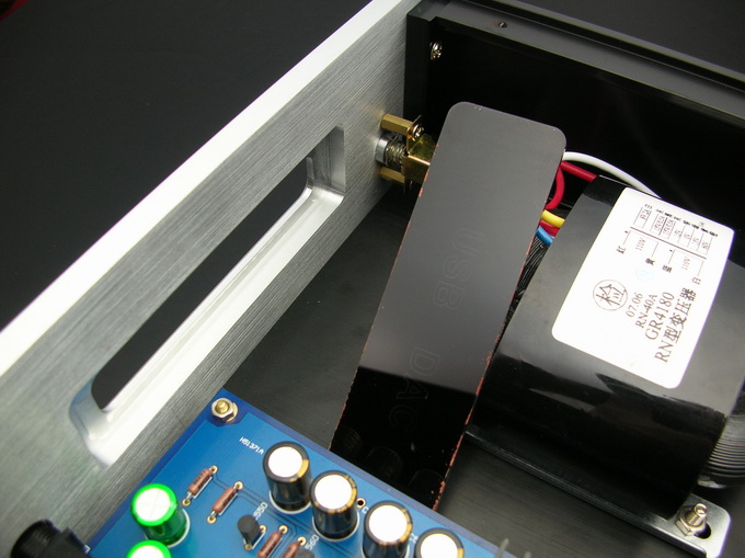
1£¬Loaded into the transformer
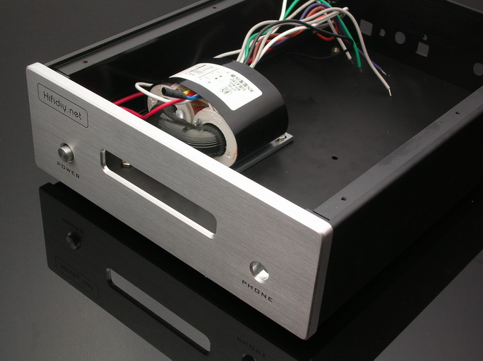
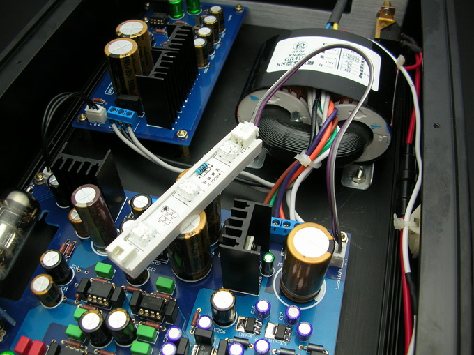
2£¬Insurance and wiring installed£¬Red for the line of fire
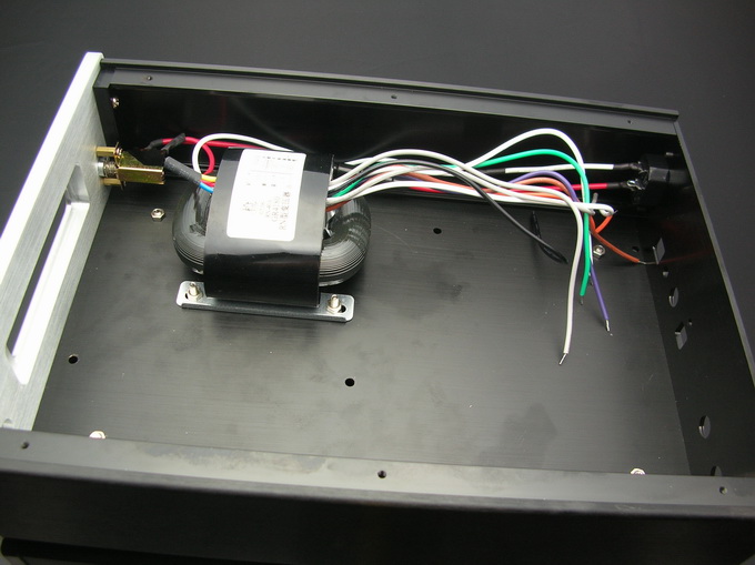
3£¬After the installation of transformers like
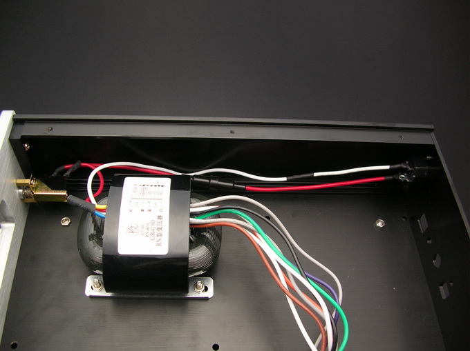
4£¬Then loaded PCB
5£¬Connection£¬Please be sure to remember the location of line£¡
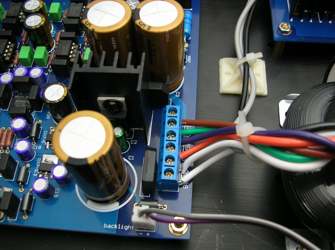
6£¬Installed to connect the line headphone amplifier board
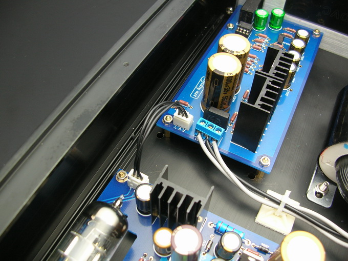
7£¬All the installation is complete£¡£¡
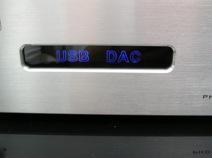
front£º
http://www.hifidiy.net/jhwz/200707/W020070713835631715719.jpg
Backlight lamps installed£º
Hot melt adhesive with a fixed background light £º
consummation£¡£¡

Power on£¡£¡
can use computer to be switched on
1)15V 0 15V 60V--------25W
2)15V 0 15V-------------15W(for headphone amplifier)
3)8V 0----------------- 16W
110V--220Vac
An externally hosted image should be here but it was not working when we last tested it.
In addition£¬We also designed a shell£¬headphone amplifier£¬then the power supply, headphone amplifier, usb tube DAC, assembled together£¬you can see£º
1£¬Loaded into the transformer
2£¬Insurance and wiring installed£¬Red for the line of fire
3£¬After the installation of transformers like
4£¬Then loaded PCB
5£¬Connection£¬Please be sure to remember the location of line£¡
6£¬Installed to connect the line headphone amplifier board
7£¬All the installation is complete£¡£¡
front£º
http://www.hifidiy.net/jhwz/200707/W020070713835631715719.jpg
Backlight lamps installed£º
Hot melt adhesive with a fixed background light £º
consummation£¡£¡
Power on£¡£¡
can use computer to be switched on
analog_sa said:Perfect design? But using a 2707?!
Have we not seen this on Ebay already?
No£¬we have not sell on ebay.
The face of low-end market, I think it is quite a good¡£
Shape design and Circuit board design£¬I think it is almost perfect¡£
Of course, we will work harder and do better
thanks
Jacky
analog_sa said:Perfect design? But using a 2707?!
Have we not seen this on Ebay already?
Then what else do you expect to use to get USB -> I2S to feed the PCM1798?
eBay maybe not, taobao and other Chinese websites, yes.

wwenze said:
Then what else do you expect to use to get USB -> I2S to feed the PCM1798?
I also use a 2707 but do not call it "perfect" as it really demands some kind of reclocking. An asyncronous chip would better fit this description.
wwenze said:
eBay maybe not,
Maybe yes
http://cgi.ebay.com/Hi-End-USB-DAC-...in_0?hash=item45eb716b7c&_trksid=p3286.c0.m14
yildiray said:perfect job.1m shocking!
whether you meant this funny or not I admit it made my day
analog_sa said:
Amazing£¡We worrking group does not sell on ebay£¬and the price is equally alarming£¡Also he buys from Chinese websites£¬then turn to sell on ebay£¬this product has listed more than a year ago
Jacky
korben69 said:Hi, what do you mean saying "the price is equally alarming" ?
Hi,Because there is a reply above that on ebay to see this product£¬so according to his link£¬I enter£¬and see the price on ebay£¬then I said "the price is equally alarming"
Jacky
- Status
- This old topic is closed. If you want to reopen this topic, contact a moderator using the "Report Post" button.
- Home
- Vendor's Bazaar
- USB tube DAC£¬High-quality£¬Perfect design