Dear all,
From now i have 2 new Products,
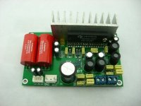
the TA2020 PCB, fully assambled and tested 25 Watt per channel.
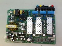
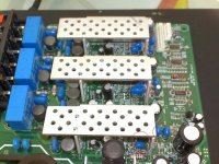
And a 6 Channel fully finished 3 X TA2020 amplifier PCB with powersupply! 6X 25 watt.
The powersupply delivers 10 A at 12 volts and the PCB has only high quality semiconductors from Fairchild, National, ONsemi and Tripath. Part numbers include:
- KA1L0880B
- MBR20100CT
- MC14069U ( for the controller section
- TA2020 X 3 ( Class-T 25 Watt amplifier IC
Pricing is:
The 2 Channel TA2020 PCB will cost 20 Euro
The 6 Channel TA2020 PCB will cost 50 Euro
Shipping via HKpost cheap and fast with insurance and traking number.
Other items on request.
Greetings,
Arjen Helder
From now i have 2 new Products,
the TA2020 PCB, fully assambled and tested 25 Watt per channel.
And a 6 Channel fully finished 3 X TA2020 amplifier PCB with powersupply! 6X 25 watt.
The powersupply delivers 10 A at 12 volts and the PCB has only high quality semiconductors from Fairchild, National, ONsemi and Tripath. Part numbers include:
- KA1L0880B
- MBR20100CT
- MC14069U ( for the controller section
- TA2020 X 3 ( Class-T 25 Watt amplifier IC
Pricing is:
The 2 Channel TA2020 PCB will cost 20 Euro
The 6 Channel TA2020 PCB will cost 50 Euro
Shipping via HKpost cheap and fast with insurance and traking number.
Other items on request.
Greetings,
Arjen Helder
Attachments
Crossoversss
Hey there GLT,
Ive seen some boards that can filter, but i doubt the quality of them,But what i can find here i can show you.
Would it be possible to fiddle with coils and caps? i think this is eazyer and more controllable.
Ive modded one board yesterday and ive seen the mods really amazingly improve the sound quality!
The input caps on this board are adjusted to match the speakers they are used with, Shitty 5.1 set's used here in China, so L/R front and back have the Bass filtered out, basicly because they have put 2 caps in series so i have bridged one of the caps and replaced the 0.1uF with 2.2 uF.
Also the Subwoofer Channel misses a 100nF cap and a 1K resistor. these need to be added to make the thing full range.
After the mod i went to listen and was amazed ! the sound now is worthy a TA2020! it took me about one hour to make the mod and about 20 CM of litz ( solder Wick )
For the less experianced DIY'er. i will be offering modded boards aswell.
Hey there GLT,
Ive seen some boards that can filter, but i doubt the quality of them,But what i can find here i can show you.
Would it be possible to fiddle with coils and caps? i think this is eazyer and more controllable.
Ive modded one board yesterday and ive seen the mods really amazingly improve the sound quality!
The input caps on this board are adjusted to match the speakers they are used with, Shitty 5.1 set's used here in China, so L/R front and back have the Bass filtered out, basicly because they have put 2 caps in series
so i have bridged one of the caps and replaced the 0.1uF with 2.2 uF.Also the Subwoofer Channel misses a 100nF cap and a 1K resistor. these need to be added to make the thing full range.
After the mod i went to listen and was amazed ! the sound now is worthy a TA2020! it took me about one hour to make the mod and about 20 CM of litz ( solder Wick )
For the less experianced DIY'er. i will be offering modded boards aswell.
ArjenShenzhen,
Thanks for the info. For my application I just need a second order low pass at around 1 KHz for 4 of the channels and no filter for the other two channels. Two channels will drive the tweeter and I have a first order high pass (one single capacitor) which I will use in order to protect the tweeter. 4 channels will drive 4 woofers (2 for L and 2 for R)
So it is very easy with opamps, but if there is something readily available, then it is easier. Since there is +/- 12v from the supply, I could even take advantage of that supply to power the opamps
Are the input caps thru hole or smt? (can you show a picture?)
Thanks.
Input caps
Hi there,
Here a photo that shows the caps, luckely they are thrue hole, so nothing to worry about.
ive put red circles arount the caps, the signal go's thrue two caps before it goes to pin 9 and 11 ( input pins on the IC )
The trick is to remove the ones you can eazely reach and to solder a wire to short out the ones you don't want. ive used poly caps as input capacitors on my trial, they work just fine, and for some extra i can add those with the board. they cost me about 3 Euro per 8 Pcs. and they have roughly the same size as the caps that need replacement.The film caps ive used before are to big to fit here, but im looking for some 100 or 63 volts film caps, that might fit.
Greetings,
Arjen helder
Attachments
GLT,
i have just finished a nice PDF explaining how to mod this board and get the best out of it, any one that wants this file, please drop me a mail and ill send it to you .
if there is any way of posting files here on the forum that are say 800 KB, i'd like to know")
Greetings,
Arjen
BTW i can also throw it true MSN, Arjenhelder using the hotmail service dot com.
i have just finished a nice PDF explaining how to mod this board and get the best out of it, any one that wants this file, please drop me a mail and ill send it to you .
if there is any way of posting files here on the forum that are say 800 KB, i'd like to know
Greetings,
Arjen
BTW i can also throw it true MSN, Arjenhelder using the hotmail service dot com.
ArjenShenzhen said:GLT,
i have just finished a nice PDF explaining how to mod this board and get the best out of it, any one that wants this file, please drop me a mail and ill send it to you .
if there is any way of posting files here on the forum that are say 800 KB, i'd like to know
Greetings,
Arjen
BTW i can also throw it true MSN, Arjenhelder using the hotmail service dot com.
Hi Arjen, could you please send me the PDF on my e-mail, I just cannot reach you on your e-mail Myny thanks Petr
Volume
Hi Arjen! I am waiting for one of your boards, (MKII PCB with 2.2uF/ 400v MKP caps) and as I am a complete electronics novice,
I was wondering about the upgrades you have mentioned ie 2x 6800microF added to power line and 2 x 470 microF added to ic input; you wrote in one of your replies that the 2.2uF was too small and needed to be larger in order to improve the (bass?) sound.
I am also wondering about volume control ( A pot is it?) I need one - right? Where and what would it connect to? (I know a fair bit of electronics theory, but have never needed to use it, until I saw these devine amps!!)
I feel I could do some of these simple mods, but have little knowledge of 'where I am on the board'. Is there a sinple diagram or simple instructions I can obtain from you or someone else?
Oh, we do put you through it - don't we?!!
Incidently, would adding tubes (6N7, 6N11), to the tripath IC design improve it's performance/sound, or is this a stupid question?
Many Kind Regards, and keep up the good work!
Tony Swaine (Chester, N.W. England)
PS My email is a.swaine@tiscali.co.uk - if anyone out there can offer any assistance as well.
TA2020
Hi there Tony,
so you ordered the MKII TA2020 PCB? not to be confused with the Topping KII right?
The PCB has all the caps needed on the board, this does not need grading according to my measurements.
The idea of making a valve Pre-amp was already in my mind and ill order today the second lot of sample PCB's, after some improvements where added. im using a 12AX7 or the ECC81 equlivant, a famous tube that has good response and the PCB has a built in DC-DC converter, so no separate powersupply is needed, just 12-14 volts, thats all!
ill post specs as soon as im done with it!
Greetings,
Arjen Helder
Pdf for T amps
Argen,
Please post some links to your pdf for the products you sell. I can find no information other than some small pics. Interested in TA2024 and TA2020 boards, particularly the 6 channel with SMPS. What do you recommend for hookup to 3.5mm stereo or RCA? What would cables like this cost for use with your TA2024 boards instead of the little 3 wire adapter?
Thanks,
Ted
Tripath PCB's
Hi there Ted, send me a mail and ill send them to you.
Arjenhelder@hotmail.com
Greetings!
Arjen
Hi there Ted, send me a mail and ill send them to you.
Arjenhelder@hotmail.com
Greetings!
Arjen
Hi Arjen!
I have ordered this from your shop on ebay:
~~~~~~~~~~~~~~~~~~~~~~~~~~~~~~~~~~~~~~~~
ebay item number 260395215821
- 1 X TA2020 PCB new version fully finished and tested ( length:11cm , width:6.3cm ,height:3cm )
* (another Back side of TA 2020 pcb board is not included,just want to show you the back side of TA2020 pcb )
- 1 X Powersupply cable
- 1 X insput signal cable
- 1 X On-Off power switch (single pole switch with light inside).
Improvements to the PCB:
-400 volts 2.2uF audio grade film capacitors! and plenty of space for upgrades!
-Connectors all situated at once side for eazy installation
-Bigger board size for more space to replace components
-Bigger output coils with a better transient response and thicker copper wire.
~~~~~~~~~~~~~~~~~~~~~~~~~~~~~~~~~~~~~~~~
Do you have a PDF for this to assist in the attatchment of Volume, Input and 12V power supply, or are these points marked on the board?
Kind Regards, and thanks for your quick reply.
Tony
a.swaine@tiscali.co.uk
TA2020 Info
Hi there Tony,
To connect a volume potmeter you have to do the following:
- every stereo potmeter has 6 pins, in 2 rows of 3. every row of 3 is one channel, so one for left and one for right.
the 2 last pins in each row can be connected to the ground wire from the PCB and from the source
the middle pins can be connected to the TA2020 PCB input
The 2 first pins can be connected to the source.
if you have connected it it looks like this:
[GND][R-amp][R-source]
[GND][L-amp][L-source]
then it should work!
all these connectors have there funtion written next to it.
Greetings,
Arjen Helder
- Status
- This old topic is closed. If you want to reopen this topic, contact a moderator using the "Report Post" button.
- Home
- Vendor's Bazaar
- New ta2020 pcb'S