Thanks Arjen, that's nice and clear.
Stupid Question Alert: Would I be able to run my Rotel 931 MKII Amp into your "25Watt TA2020 PCB new version fully finished and tested" amp; as people are raving about the sound quality of the Tripath TA2020? Or could I use the TA2020 as a preamp instead?
Thanks again, Tony Swaine
Stupid Question Alert: Would I be able to run my Rotel 931 MKII Amp into your "25Watt TA2020 PCB new version fully finished and tested" amp; as people are raving about the sound quality of the Tripath TA2020? Or could I use the TA2020 as a preamp instead?
Thanks again, Tony Swaine
A pre-amp is basically a control unit that regulates the volume and allowes you to switch between input sources. An integrated amplifier consists of a built i pre amp and a power amplifier.
You could use the Rotel as a pre-amp if it has pre out exits. The TA 2020 which is a power amplifier should definitively not be used as a pre-amp.
You could use the Rotel as a pre-amp if it has pre out exits. The TA 2020 which is a power amplifier should definitively not be used as a pre-amp.
Hi! In reply to Arjen and Morglo (posts #20 & #23): Arjen I am stunned and amazed at the power and quality of this tiny amp - the size of a fag packet!
I am running the amp (12V 2A DC supply) into 2x physically large 8 Ohm speakers, but without the pot, the volume was too high for comfort; but now it's exquisite!
I have setup the "TA2020 PCB new version fully finished and tested" amp with a 100K volume pot and a 22k resistor on the output/GND (middle/2nd)/ (right/3rd) pins, as suggested here:http://sound.westhost.com/project01.htm
This was to inprove the characteristics of the pot to enable a more Log Pot S curve response/sound.
I have noticed a slight thump through the speakers, when I switch on the amp, but I am not at all concerned by this, as I have had this on a NAD 3020, and my current Rotel 931 mkII does the same thing.
Is this a 'power surge'?
I saw somewhere, of a configuration where someone had a resistor and a capacitor connected in-line just after the power in. What might that have been for?
I cannot wait for the valve preamp TA 2020!
Many thanks, Tony Swaine
ta2020
Hi Arjen,
i'm the same guy who message u thru ebay.
question, can i use one pcb for one speaker and ttherefore each one output 25w?
is the new ta2020 model that u are launching soon, sonically better than the existing one?
i am referring to the model that output 25w with 2 orange or res caps by the side.
cheers....
twinney12 said:
I have setup the "TA2020 PCB new version fully finished and tested" amp with a 100K volume pot and a 22k resistor on the output/GND (middle/2nd)/ (right/3rd) pins, as suggested here:http://sound.westhost.com/project01.htm
Tony Swaine
Tony, I will be getting the same MKII Version of TA2020 and will be adding the volume pot.
Any recommendation on how to do it on this board?
gychang
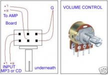
Hi! This was sent me by Arjen:"To connect a volume potmeter you have to do the following:
- every stereo potmeter has 6 pins, in 2 rows of 3. every row of 3 is one channel, so one for left and one for right.
the 2 last pins in each row can be connected to the ground wire from the PCB and from the source
the middle pins can be connected to the TA2020 PCB input
The 2 first pins can be connected to the source.
if you have connected it it looks like this:
[R-source][R-amp][GND]
[R-source][L-amp][GND]
then it should work!
all these connectors should have there function written next to it
"
See the picture I've included, and orientate your pot in same way - ie turn it upside down with the pins sticking up, and the knurled knob facing you.
(From my post to Arhen: I am running the amp (12V 2A DC supply) into 2x physically large 8 Ohm speakers, but without the pot, the volume was too high for comfort; but now it's exquisite!
I have setup the "TA2020 PCB new version fully finished and tested" amp with a 100K volume pot and a 22k resistor on the output/GND (middle/2nd)/ (right/3rd) pins, as suggested here:http://sound.westhost.com/project01.htm
This was to improve the characteristics of the pot to enable a more Log Pot S curve response/sound.")
That is:
1. connect top left pin to right channel from cd output (or whatever source).
2. connect top middle pin to right channel connector R input on pcb board (or whatever source).
3. Top R pin on pot to ground (or earth) on the board.
4. Connect 22k resistor BETWEEN top middle and top R pins on pot.
You place the pot between the output of your source (CD?) and the Input of the Tripath board.
Attachments
To gychang:
SEE MY POST ABOVE
Hi! Forgot to mention that there is no space for the pot on the board, so you will have to mount it on the panel of the container you put Tripath PCB into.
PS If you have a pot with 4 pins at top and 4 below, the pins on left end would most likely have been used for a 'loudness' filter, and can be ignored. (Orientate pot as in pic above).
To Mattcalf:
The output from the preamp connects to the R GND L input on the Tripath - the smaller white female connector socket.
This
"[R-source][R-amp][GND]
[R-source][L-amp][GND]"
in post #29
should, of course be:
[R-source][R-amp][GND]
[L-source][L-amp][GND]
Kind Regards, Tony Swaine
Volume control
The new MKIII board has space for a small sized potmeter, just one size smaller then the usual, but not many people use it sice you'd want to have the potmeter on the front plate of the housing anyway.
if there's any trouble connecting then post it, ill try to answer!
im really busy these days so it might take 2 days...
Greetings,
Arjen
Arjen: input selector connection?
I received the MKIII Tripath TA2020 PCB 25watt Class-T amplifier SET today from you. Looks to be hiqh quality, carefully packaged but have not yet connected for testing.
Previous discussions gives me clear idea on how to hookup pot, but my question is regarding the input selector switch. Is there an easy to follow instruction somewhere? (I also sent u an email). May be this is a better format so others who order the unit can see.
gychang
Selector switch
Hi there,
Connecting the selector switch is eazy when observing the switch carefully,
The inner pins, 3 Pcs, are your output, they go to the volume potmeter and then to the amplifier.
the outer pins are the input pins.
Now if you turn the knob all the way counter clockwise, you can see there are 3 lips inside the switch, touching the pins on the outside. now you can connect the wires to the pins that touch that lip, click the switch further one notch and start with the next channel, one notch further and solder the third channel, and then your done!
ill make a photo of mine later and post it.
GReetings,
Arjen Helder
Re: Selector switch
Thanks, I have the general idea, will wait for the picture.
gychang
ArjenShenzhen said:Hi there,
Connecting the selector switch is eazy when observing the switch carefully,
The inner pins, 3 Pcs, are your output, they go to the volume potmeter and then to the amplifier.
the outer pins are the input pins.
Now if you turn the knob all the way counter clockwise, you can see there are 3 lips inside the switch, touching the pins on the outside. now you can connect the wires to the pins that touch that lip, click the switch further one notch and start with the next channel, one notch further and solder the third channel, and then your done!
ill make a photo of mine later and post it.
GReetings,
Arjen Helder
Thanks, I have the general idea, will wait for the picture.
gychang
glt said:ArjenShenzhen
Do the caps have to be close to the input circuitry? Otherwise you can short all the caps and add them at the input wires. Thanks.
hi i buy your 6 channel pcb but I've a problem with the connection to 220V and the 2,2 capacitors included in the kit,you can send me a pdf manual? tnx
hi ArjenShenzhen and all users on this 3d, I got a 6 your channel pcb and now it's work great, but on pdf file i don't understand where is the capacitors which must change to obtain the full range frequency or improved the bass( the replace cap value are 2.2 mF) tnx to all
great! i'm waiting your photo!mattcalf said:My board and PSU arrived today, will post later down the trackwhen i get it working. (When my wrist isn't broken
twinney12 said:Arjen I am stunned and amazed at the power and quality of this tiny amp - the size of a fag packet!
I am running the amp (12V 2A DC supply) into 2x physically large 8 Ohm speakers, but without the pot, the volume was too high for comfort; but now it's exquisite!
Many thanks, Tony Swaine
Tony does the included power switch illuminated?, does it contain a small LED?
gychang
- Status
- This old topic is closed. If you want to reopen this topic, contact a moderator using the "Report Post" button.
- Home
- Vendor's Bazaar
- New ta2020 pcb'S