pinkmouse said:If the pinouts are the same, could you sneak the holes out from under the inductor a little so a TO220 would fit?
Probably not...

Seriously space constrained....
Ok Pinkmouse, and Jean-Paul
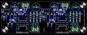
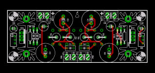
What do you think of this PS configuration?
It has TO-2020 package(with plenty of heat sink) and the sensitive nets are far away from the rectifiers.
Only two SMD devices, little common mode chokes from Murata. The are 1206 package, not too hard to solder, but if people really want we could probably supply them already mounted.
Cheers!
Russ
Attachments
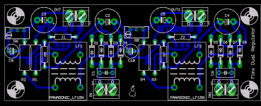
jean-paul said:OK, I go with the flow. R6+C8 and R8+C10 could move a few millimeters down. They touch both the heatsink and the mounting hole.
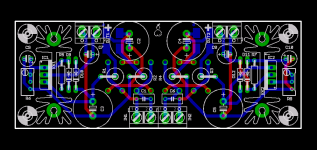
The heatsinks will not be needed when low voltage transfomers will be used but they make the design indeed suitable for other projects.
Ah yes, thanks!
As for the heat sinks, they could be omitted or could be changed for smaller types.
Cheers!
Russ
Attachments
They will only get warm if the transformer is of a higher voltage. Let us say 2 x 12V. The LM317 have to dissipate nearly 0.4 to 0.5 W then. One of the reasons I don't like preregs, a small waste of energy
The older non-LDO like LM317 need at least 3V over them to work correctly so lower voltage transformers like 2 x 6V are a bit tight in voltage. They should manage however as LP2985-5 only needs max. 300 mV over itself. Let us define its input voltage should be 5.5V or more.
An Amplimo ( 08010 ) 2 x 6V 1.25 A will give more than 7V with this light load. 7V x 1.4 = 9.8V. 9.8V - ( 2 x Uf 0.45 of the diodes )= 8.9V. This is with Schottky diodes like 11DQ10.
8.9V - ( 3V of LM317 ) = 5.9V. We need max. 0.3V at 150 mA load for the LP2985-5 so it will work. LM317 can be adjusted to 5.5V output. Best is to use low dropout Schottky diodes like 11NQ10 for a normal margin ( or use LDO regs instead of LM317 ).
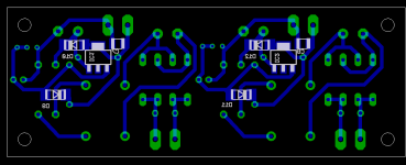
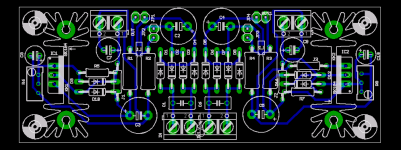
Final power supply PCB for review
OK Folks, if this PS looks OK the whole mess of board gets ordered tomorrow.
So, this is your last chance to request a change.
Switched choke coils to TDK ACM0706-102-2P-X common mode chokes. I think will work to good effect, if not, please feel free to suggest another part of similar size.
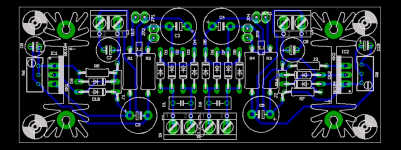
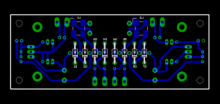
Also the layout is now double sided.
The rectifiers and the coils go on the bottom, the rest of the compoents are mounted top side.
Cheers!
Russ
OK Folks, if this PS looks OK the whole mess of board gets ordered tomorrow.
So, this is your last chance to request a change.
Switched choke coils to TDK ACM0706-102-2P-X common mode chokes. I think will work to good effect, if not, please feel free to suggest another part of similar size.
Also the layout is now double sided.
The rectifiers and the coils go on the bottom, the rest of the compoents are mounted top side.
Cheers!
Russ
Attachments
- Status
- This old topic is closed. If you want to reopen this topic, contact a moderator using the "Report Post" button.
- Home
- More Vendors...
- Twisted Pear
- Mr White's "Opus", designing a simple balanced DAC