Hey all, I have a quick question in regards to the SE's output when used in voltage mode (I/V distinction may even be irrelevant to the answer).
Is the output active-balanced or impedance-balanced? Meaning is there a signal on the + and - pins, or is the - pin just impedance matched to the + pin?
Thanks!
The outputs are true balanced outputs.
Thank you Brian.The outputs are true balanced outputs.
I'm not familiar with IIISE version, but with Buffalo II
If I remember correctly,
each phase has maximum voltage swing of AVCC*0.9/2 or so, depends on the load.
high value load = more voltage swing, less current swing
low value load = less voltage swing, more current swing
virtual GND, near zero ohm = nearly no voltageswing, full current output
If I remember correctly,
each phase has maximum voltage swing of AVCC*0.9/2 or so, depends on the load.
high value load = more voltage swing, less current swing
low value load = less voltage swing, more current swing
virtual GND, near zero ohm = nearly no voltageswing, full current output
Thanks for the reply!
Just a thought, with these levels, why would one need a legato, ivy d1 or anything else, and not connect the output of the dac to an i/v resistor and then straight to a power amp, say a NCORE?
Given (of course) that everything would be in the same box.
Just a thought, with these levels, why would one need a legato, ivy d1 or anything else, and not connect the output of the dac to an i/v resistor and then straight to a power amp, say a NCORE?
Given (of course) that everything would be in the same box.
It should be necessary to squeeze better THD performance.
described in the whitepaper, page4
http://www.esstech.com/PDF/sabrewp.pdf
I personally have positive experience with voltage mode - outputs followed by transformers
Good locational presentation, while it does not harm the fidelity so much.
described in the whitepaper, page4
http://www.esstech.com/PDF/sabrewp.pdf
I personally have positive experience with voltage mode - outputs followed by transformers
Good locational presentation, while it does not harm the fidelity so much.
Last edited:
The ES9018's outputs are not strictly current-output, like many other DACs. Using an I/V R directly on the outputs will induce modulation of the DAC's output stages resulting in increased distortion.
If you want to bypass an output stage (and filtering), it would be better to drive the N-cores directly, though the performance will not be a good as if you used a proper active I/V stage (near 0 input impedance).
If you want to bypass an output stage (and filtering), it would be better to drive the N-cores directly, though the performance will not be a good as if you used a proper active I/V stage (near 0 input impedance).
what is the output voltage to the "lock" led? and which is the current-set resistor for the led? - thinking about using a blue led there which does have ~3.2v forward voltage.
Blue LEDs usually require a lot more current, and could damage the ES9018, unless you add a buffer (R+Q). Off the top of my head, it is 3.3V. The resistor is easy to find, just follow the trace back toward the chip (at work, so I cannot look).
S/PDIF & Ground shorted out
I have not had my board hooked up yet. While waiting for other parts, decided to solder on the uFL sockets onto the board—I did the s/pdif first, since until I have a USB interface, I'll be using toslink. After I soldered it, I tested continuity, and the ground and s/pdif were shorted. So I unsoldered the connector, thinking that I must have gotten a solder bridge under it. No—all was clean. It is still shorting though, which I can't imagine is correct. The pads are clean, there is no visible solder to connect them. Is it possible that solder got into the mid layers? Any way to fix this? If not, will this affect the PCM/DSD input? I used very little solder—.015 diam. with a rtiny tip (.020?) on my Hakko. Heat was at 640 F.
I have not had my board hooked up yet. While waiting for other parts, decided to solder on the uFL sockets onto the board—I did the s/pdif first, since until I have a USB interface, I'll be using toslink. After I soldered it, I tested continuity, and the ground and s/pdif were shorted. So I unsoldered the connector, thinking that I must have gotten a solder bridge under it. No—all was clean. It is still shorting though, which I can't imagine is correct. The pads are clean, there is no visible solder to connect them. Is it possible that solder got into the mid layers? Any way to fix this? If not, will this affect the PCM/DSD input? I used very little solder—.015 diam. with a rtiny tip (.020?) on my Hakko. Heat was at 640 F.
Could you check this Brian? 3-4mA ok?")
R2 and R5 feed the LEDs. They are both 357R, yielding roughly 9mA to the LEDs.
I have not had my board hooked up yet. While waiting for other parts, decided to solder on the uFL sockets onto the board—I did the s/pdif first, since until I have a USB interface, I'll be using toslink. After I soldered it, I tested continuity, and the ground and s/pdif were shorted. So I unsoldered the connector, thinking that I must have gotten a solder bridge under it. No—all was clean. It is still shorting though, which I can't imagine is correct. The pads are clean, there is no visible solder to connect them. Is it possible that solder got into the mid layers? Any way to fix this? If not, will this affect the PCM/DSD input? I used very little solder—.015 diam. with a rtiny tip (.020?) on my Hakko. Heat was at 640 F.
Can you post a picture of the pads?
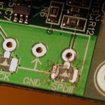
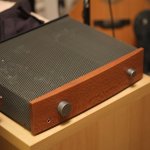
Here's a macro shot with low angled lighting. I'm including a quick shot of the housing I've made while waiting the 5 months for the final parts (MJE for BP supply, Mouser is shipping this week!!)
I like the case very much, not sure about the soldering though
I shouldn't talk I fried a track to the lock light & had to do a micro repair, you might be able to do a similar thing, if you can work out where the grounding is occurring.
Last edited:
I'm hoping to. The soldering didn't look bad, until I had to solderwick off the connector and then, when it was still shorted, kept using more solderwick in the area to soak up as much as I could. But obviously I did screw something up with the soldering. For work I've been building small boards with many 0603 LEDs on them, and felt pretty confident about putting the uFL connectors on. I've looked at the immediate area with a 20x scope (boy is it nasty looking at that scale!) and from the board exterior don't see any bridging. There are those tiny holes around the ground pads, and my worry is that somehow solder went through those and might be shorting traces in the mid layer. If that's the case, then the only fix I can imagine would be grinding away the uFL area pad connectors there to get inside—but certainly want to wait until I get Brian's answer about whether the short could be happening in a mid layer (1) and if I grind away just that area (say the rectangle defined by the outer edges of the two uFL ground pads) are there other traces in the mid layers that I'd be totally mucking with (2).
Thanks about the case—the front is wood from your neck of the woods—Australian Lacewood.
Thanks about the case—the front is wood from your neck of the woods—Australian Lacewood.
- Status
- This old topic is closed. If you want to reopen this topic, contact a moderator using the "Report Post" button.
- Home
- More Vendors...
- Twisted Pear
- Buffalo III - SE