Any issues with chaining OTTO's? I have a USB to i2s converter, the MUX, and the DSD output from my SACD player via Teleporter to input to my Buffalo II. I thought I could use one OTTO to switch between the MUX and the SACD and output to another OTTO to switch between OTTO #1 and the USB to i2s converter. Would this cause any problems?
Stated more simply, three i2s sources(1, 2, 3), two OTTOS(A, B).
1 & 2 switched with OTTO A.
3 and OTTO A switched with OTTO B connected to the Buffalo II.
I could keep all the wires very short, stacking the OTTOS.
Thank you for your time and help.
-Aaron.
That should work fine.
")
Because it is good engineering practice. It keeps drains and sources referenced to GND even if they are left open.
It is a mux/demux so what is an input or an output is totally up to you.
Of course you can omit them. But I wouldn't. They do no harm.
So what resistor banks should I buy for switching between SPDIF inputs?
Hello, I'm using a otto2 to switch between i2s and spdif using a switch. Operating properly. I would like to place an LED to indicate signal which is in use, how I can do it with otto2?. Thank you!
You could use a 3 Pole Double Terminal switch, (3PDT)
Any issues with chaining OTTO's? I have a USB to i2s converter, the MUX, and the DSD output from my SACD player via Teleporter to input to my Buffalo II. I thought I could use one OTTO to switch between the MUX and the SACD and output to another OTTO to switch between OTTO #1 and the USB to i2s converter. Would this cause any problems?
Stated more simply, three i2s sources(1, 2, 3), two OTTOS(A, B).
1 & 2 switched with OTTO A.
3 and OTTO A switched with OTTO B connected to the Buffalo II.
I could keep all the wires very short, stacking the OTTOS.
Thank you for your time and help.
-Aaron.
That should be fine. It will come down to keeping the wiring neat.
Yes, and no
The short answer is yes, there will be no problems. The long answer is no, as anything placed in the I2S signal path will damage the signal somewhat, resulting in some additional jitter. Make sure to keep I2S wiring as short as is possible as well.
I personally prefer to have a single I2S source, wired directly to my DAC (B-IIIse) with 5 mm U.FL cables, to keep form having any compromise at all in the I2S signal.
i forgot to ask - if using external MCK from say two i2s sources - does this "switch" really work problem free with up to 100MHz?
The short answer is yes, there will be no problems. The long answer is no, as anything placed in the I2S signal path will damage the signal somewhat, resulting in some additional jitter. Make sure to keep I2S wiring as short as is possible as well.
I personally prefer to have a single I2S source, wired directly to my DAC (B-IIIse) with 5 mm U.FL cables, to keep form having any compromise at all in the I2S signal.
The short answer is yes, there will be no problems. The long answer is no, as anything placed in the I2S signal path will damage the signal somewhat, resulting in some additional jitter.
With a maximum propagation delay of .25nS, and that value likely to be similar or equal among the four bus channels on the chip, the amount of jitter introduced will be negligible at 100MHz. You would begin to worry about it above 400MHz, and even then it would be minimal.
I'm doing some mods & want to loose the relay but also want to be sure I've got this right.
It is my understanding from what I have read that;
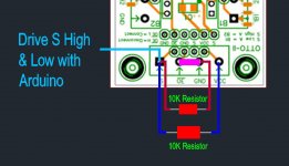
* I have a 10k resistor between S & GRND
* I have a 10k resistor between S & VCC
* I have a link between OE & Grnd
* I drive S High & Low with Arduino
Is that correct?
It is my understanding from what I have read that;
* I have a 10k resistor between S & GRND
* I have a 10k resistor between S & VCC
* I have a link between OE & Grnd
* I drive S High & Low with Arduino
Is that correct?
Attachments
You will notice there are pads for installing pull-up/down Rs behind the terminal block.
As for control if you are using 3.3V logic you don't need the pullup unless you are using an open drain type output.
Cheers!
Russ
Your answer raised more questions than answers and hasn't helped me at all.
I was hoping for something simple like:
Yes that is correct
OR
No that is not correct, do this.??
Thanks,
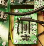
I've linked OE to Grnd, put a 10k resistor between S & Ground & an driving S High & Low with an Arduino output & it is working, although I'm going to have to change the code as I'm now getting a mirrored result to when I was using the relay.
You cant see the Arduino connection in the pic as its under the board.
Attachments
I'm thinking of going with the OTTOII for an upcoming project I'm working on. The idea is to switch between two i2s sources -- BBB and Amanero. The goal is to have both sources have synchronous clocking utilizing the Acko S03 board, which will be going to one of Acko's ES9023 based DACs.
The question is the OTTOII up to the task?
I'm thinking this is how it'd work...
Amanero in slave mode sends just LRCK, BCK, and SDATA to OTTOII. BBB using Botic driver (hopefully integrated with RuneAudio) sends just LRCK, BCK, SDATA to OTTOII. Have a way to switch between them... perhaps a SPST switch? Then these 3 signals go to Acko S03 U.FL inputs. Then both i2s transports will receive MCK from Acko S03. I'll have to figure out a way to spit out two instances of clock simultaneously. I don't think this will be hard because the pin headers and U.FL sockets seem to be the same path. I won't divide clocks and they'll be 45/49Mhz flavors. I haven't figured how to do CLK select yet, but that would be the only challenge I can foresee.
Any reason why this wouldn't work?
I'm thinking of going with the OTTOII for an upcoming project I'm working on. The idea is to switch between two i2s sources -- BBB and Amanero. The goal is to have both sources have synchronous clocking utilizing the Acko S03 board, which will be going to one of Acko's ES9023 based DACs.
The question is the OTTOII up to the task?
I'm thinking this is how it'd work...
Amanero in slave mode sends just LRCK, BCK, and SDATA to OTTOII. BBB using Botic driver (hopefully integrated with RuneAudio) sends just LRCK, BCK, SDATA to OTTOII. Have a way to switch between them... perhaps a SPST switch? Then these 3 signals go to Acko S03 U.FL inputs. Then both i2s transports will receive MCK from Acko S03. I'll have to figure out a way to spit out two instances of clock simultaneously. I don't think this will be hard because the pin headers and U.FL sockets seem to be the same path. I won't divide clocks and they'll be 45/49Mhz flavors. I haven't figured how to do CLK select yet, but that would be the only challenge I can foresee.
Any reason why this wouldn't work?
I cannot see any reason it wont work although I've only ever used mine for switching SPDIF, it has 4 inputs on either side. I'm not sure what the switching chip is so no way of checking the data sheets. The Product info says;
The OTTO-II Digital Switching module is a simple 4-channel 2:1 switch which allows you to connect and switch between two digital data lines (I2S, DSD, S/PDIF, etc) to a single digital input out output. Typically it wil be used to select between two digital sources and a single DAC, but could also be used to, say, select a DAC from a single digital source.
- Status
- This old topic is closed. If you want to reopen this topic, contact a moderator using the "Report Post" button.
- Home
- More Vendors...
- Twisted Pear
- Introducing OTTO2