
Hi Acidbrain,
Russ replied to met that the ground should also go through the teleporter.
Look here
I take the I2S signal from my cdpro2 like this:
CDPRO2 --> Teleporter --> Teleporter --> Metronome --> Sidecar --> DAC.
I'll be using Cat.6 cable. The provides more headroom, but Cat5 can handle the signals from the teleporter.
I Totally agree.A drawing of some kind would be helpful.
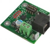
The 4 inputs closed to the boards are to connect the signals coming from a source. So the ground should probably be connected to one of the GND inputs (second row) behind the row of inputs, Right? If so, does it matter to which GND input it is connected?
Attachments
Last edited:
So the cdpro would be the only device that is not fysically connected with the shared gnd of my system. (only using i2s, mains earth cd-chassis is not connected to gnd )
This isolating has advantages, the same Russ mentioned earlier ?
You could answer later Brian, handsfree texting while driving is rather difficult")
This isolating has advantages, the same Russ mentioned earlier ?
You could answer later Brian, handsfree texting while driving is rather difficult
Last edited:
Reconnected the pc sp/dif to Buffalo Sabre II via coax and no drop outs.
Either the teleporters are sensitive or the UTP Cat5 should be shielded,
the length is 100ft.
Either the teleporters are sensitive or the UTP Cat5 should be shielded,
the length is 100ft.
Thanks for the responses.
As to the ground potential difference, probably. The dac is in the living room and pc is in the kitchen, different AC lines. Getting them well grounded
could be a problem, our home built in the 50's is two wire not the three wire system.
Didn't have the lock problems when using coax to send sp/dif. Ground on cable saved the day? But I was going into the spdif-reciever then into the dac I2S inputs.
--------------------------------------------------------------------------------------
Just tried connecting pc&teleporter ground via a long wire to the dac ps.
Before connecting wire to dac I measured .23dcv & .9acv between ground wire and dac ps ground.
It did not make a difference. Lights, refrigerator motor starts/stops still cause unlocks!
I first tried the teleporters between a Phillips CD80 and the BII to transmit I2S signals. Can't recall now, if the lock problem occurred then. Both devices were on the same AC outlet. But, between every track there was a squelch. The I2S signal was tapped at the decoder output. I tried tapping at the SAA7220/DigitalFilter outputs tp the dac, but that wouldn't fly. I seem to recall that the 7220 level shifted the output to the dac for some reason!?
I had lock problems with Teleporters in my Denon 3910 to my BIII DAC. The 3910 did not have a ground lug on the IEC socket. It was like that from the factory. Installing an IEC socket with ground lug and attaching a chassis ground to it fixed my lock problem.
I have to go back in and connect my I2S grounds to the Teleporters based on Russ's post. To the ground row, not to a channel position, in the DAC and CD player.
We have a powered reclining chair in the listening room. Anytime the wife reclined the chair, I lost lock, the sound cuts out. This was after my Denon ground fix. My system is on a dedicated 20 amp isolated ground circuit, the chair is on a different circuit. Is that still DC through the mains or I need to put the covers back on the DAC and CD player?
HI,
I have the teleporters up and running.
PC->Teradac Terelink module via I2s ->Teleporter->6'cat5->Teleporter->I2s input on sidecar.
Set the transmit teleporter to open/off and the receiver teleporter to closed/on.
Tony- I have the module, you may have the cased teradac. But I use this for connections and it works. LRCK->D1/LRCK, Data->D2/Data, SCLK->BCK, no ground connection.
I made a little lm7802 ps @ 4.8v for the teradac/pc end and used the lcdps @5.0v in the dac case to power the teleporters.
After reading some threads I set the SW1 #5 and #8 on, SW2 #5 and #8 on, all other switches off. I now can use the teradac usb-i2s converter without the constant dropouts I had before. In the past the teradac was unusable via i2s. I could use it with the spdif out but the i2s sounds better. The dac will still drop the signal occasionally but is usable. SQ is very close the the shigaclone transport when using the i2s connection on the teradac.
Teleporter received (after it's laborious journey through British customs), powered up, DIP switches on Teleporters set as per the above. Connected as follows (Teralink to Buffalo II) :- SLCK - DCK, LRCK - D1, Data - D2, plus ground to rearmost set of connectors as per previous post.
Dual-mono so both SP/DIF switches set to off, equal-length (6mm) connections to both DACs. Both lock LEDs on and rock steady, but no sound, not a peep!
My immediate suspicion falls on the Teralink and if that's the case, I've got an alternative USB - I2S board on its way so not a major issue, but I'd be very grateful if someone cold confirm I've got the connections and switches set correctly.
I'd like to tap I2S signals from my squeezebox boom and use a teleporter to connect an external DAC. I suppose the source signals are referenced to ground.
May I directly connect I2S in the squeezebox to the inputs of teleporter? Or should I insert a capacitor or a pulse transformer?
Thank you.
Paul
May I directly connect I2S in the squeezebox to the inputs of teleporter? Or should I insert a capacitor or a pulse transformer?
Thank you.
Paul
I need to put the covers back on the DAC and CD player?
Yes, sounds like a shielding/EMI issue. Could be at the DAC or the Source.
I'd like to tap I2S signals from my squeezebox boom and use a teleporter to connect an external DAC. I suppose the source signals are referenced to ground.
May I directly connect I2S in the squeezebox to the inputs of teleporter? Or should I insert a capacitor or a pulse transformer?
Thank you.
Paul
Direct. You would not want to use a transformer or cap because you need the PCM signals to go down to DC. They are not only AC signals.
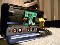
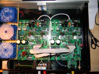
For interested on the subject - take a look at the photos.
This is how Teleporter is implemented in my setup. In this case, transmitting side is SB Touch and signal goes into FDA-1 DAC. Normally I use only 6 feet cat 5e cable but initial tests were done on up to 30 foot lengths resulting in success. If I wanted to make some comments or remarks and maybe help others how to properly implement Teleporter I'd say that first of all make sure you have correctly tapped I2S signal from your digital source. Of course this doesn't apply to those who already own devices with I2S output. Having that done, test your connection "short hardwired" - simply put your source and DAC side by side and use max up to 20cm or 8" wires to inject I2S. Keep in mind that probably you need to tweak that connection. Some setups require ground connection along signal, some not. Others need master clock - SCK to operate, again others not. Just experiment until you hear desired effect (clear, undistorted music). If this step is successful then keep moving on. Assuming you mark which wire carries which signal it's time for Teleporters. Speaking about power supply - you don't need anything fancy. It would be just enough to use 5V from anywhere in your enclosure. If you have time and energy make something dedicated but I use 5V right from the SB Touch power plug and everything works perfectly. Notice it is switching, "polluting" power supply ! Teleporter is small and very manageable but it will not fit into SB Touch case, unless stripped of Ethernet socket and power connector. Connecting I2S signal to Teleporters make sure you follow exactly the same pattern on both ends (receiver and transmitter). Don't forget about setting Teleporter jumpers into right modes ( one is receiver, other transmitter) and making ground connection (I2S neighbouring parallel row of pins). Once done, test it on short cat 5e cable and only then extend if it works.
My experience taught me that Teleporters setup can be very sensitive to external factors. Particularly to nasty spikes in power lines and electrical fields generated for example by ionizer. This is empowered by having very long cable going near power lines or devices with higher voltage creating some potential differences in the length. I spent whole evening battling over the problem only to find out later that everything was fine after moving away from that ionizer thing. Shielded Ethernet cable may help. Keeping I2S wires before Teleporter board as short as possible also eliminates chances of pickup any electromagnetic "trash".
This is how Teleporter is implemented in my setup. In this case, transmitting side is SB Touch and signal goes into FDA-1 DAC. Normally I use only 6 feet cat 5e cable but initial tests were done on up to 30 foot lengths resulting in success. If I wanted to make some comments or remarks and maybe help others how to properly implement Teleporter I'd say that first of all make sure you have correctly tapped I2S signal from your digital source. Of course this doesn't apply to those who already own devices with I2S output. Having that done, test your connection "short hardwired" - simply put your source and DAC side by side and use max up to 20cm or 8" wires to inject I2S. Keep in mind that probably you need to tweak that connection. Some setups require ground connection along signal, some not. Others need master clock - SCK to operate, again others not. Just experiment until you hear desired effect (clear, undistorted music). If this step is successful then keep moving on. Assuming you mark which wire carries which signal it's time for Teleporters. Speaking about power supply - you don't need anything fancy. It would be just enough to use 5V from anywhere in your enclosure. If you have time and energy make something dedicated but I use 5V right from the SB Touch power plug and everything works perfectly. Notice it is switching, "polluting" power supply ! Teleporter is small and very manageable but it will not fit into SB Touch case, unless stripped of Ethernet socket and power connector
. Connecting I2S signal to Teleporters make sure you follow exactly the same pattern on both ends (receiver and transmitter). Don't forget about setting Teleporter jumpers into right modes ( one is receiver, other transmitter) and making ground connection (I2S neighbouring parallel row of pins). Once done, test it on short cat 5e cable and only then extend if it works. My experience taught me that Teleporters setup can be very sensitive to external factors. Particularly to nasty spikes in power lines and electrical fields generated for example by ionizer. This is empowered by having very long cable going near power lines or devices with higher voltage creating some potential differences in the length. I spent whole evening battling over the problem only to find out later that everything was fine after moving away from that ionizer thing. Shielded Ethernet cable may help. Keeping I2S wires before Teleporter board as short as possible also eliminates chances of pickup any electromagnetic "trash".
Attachments
Last edited:
For interested on the subject - take a look at the photos.
Nice job on the Touch I2S/Teleporter Thomas. I'm interested in doing that as I use a SB Touch for the majority of my listening. My CD player PCM/DSD out is just for BYO (bring your own) music meets. Do you have pics with the Touch's I2S tap locations?
Thanks SCompRacer
Getting I2S from SB Touch is pretty straightforward procedure however requires very good eye, steady hand and thin wires. After you get your Touch disassembled, you''ll notice numerous testing points (TP) on the PCB. The ones you're interested in are located near AKM4420 dac chip. These are:
TP 260 (Bit Clk), TP 267 (Word Clk) and TP 269 (Data). Markings in my Touch were quite smeared and unreadable so looking at the AKM datasheet eased my life. You can find it here:
http://www.asahi-kasei.co.jp/akm/en/product/ak4420/ak4420_f06e.pdf
Depending on your setup you may need also Master Clock (SCK) which you can retrieve from pin 4 of dac chip. Same signal you'll find on the inverter located between oscillator crystals - just easier to solder.
Don't forget about ground node and of course keep those wires as short as possible. Mines have no more than 1.5". I simply drilled the hole in the enclosure right over the dac chip to get them through. Putting blob of hot glue etc. on the wire solder area before assembling the Touch, keeps the wires secure.
Did not make any photos but browsing the web brings some eg.
K&K Audio / Lundahl Transformers
Touch I2S-out and Clock-in mods
Some people question whether it is worth doing this mod as long as you not bring external clock in. IMO the difference between Touch SPDIF and I2S outputs is subtle but definitely there is and it's worth every effort
Last edited:
- Home
- More Vendors...
- Twisted Pear
- Introducing the bit "Teleporter"