According to the schematic of the switch, that is the correct behavior. The power is only to power the LEDs and not needed for switching.
The switch basically alternates between open connection and gnd. If you want to mimic this with arduino, then
Open = set the pin as input, write LOW to disable the pull up resistor so that it is basically an open circuit
Gnd = set the pin as output and write LOW
In this case, since you are not applying any voltage to the pins, you might not need the level converter (there are no levels to be converted)
This is how it works:
The inputs are detected by the on-board microprocessor and the microprocessor does the register programming accordingly. If there is no input the local circuitry pulls that input pin High, so the processor would read that input a high or "1", if you ground that input, then the processor would read that input as LOW or "zero"
Last edited:
According to the schematic of the switch, that is the correct behavior. The power is only to power the LEDs and not needed for switching.
The switch basically alternates between open connection and gnd. If you want to mimic this with arduino, then
Open = set the pin as input, write LOW to disable the pull up resistor so that it is basically an open circuit
Gnd = set the pin as output and write LOW
In this case, since you are not applying any voltage to the pins, you might not need the level converter (there are no levels to be converted)
Glt
I had just come to the computer to report the same thing, as I just had the opportunity to test the 6 & 8 pins & as you already know they have 3.3v on them.
My plan was to (because I'm coding challenged) use a couple of tiny solid state relays I have as switches, & trigger them with the code I have already written.
I have no idea how to change an Input to a Output mid code, I thought they where either set as one or the other in the void setup and then left that way.
I am a carpenter so I can read plans, not schematics
") which is only too evident by my reading of the switch schematic.
which is only too evident by my reading of the switch schematic.Bye the way, thanks for your help.
I may have upset things in the BIII with my little mistake, because after the mishap I reconnected the switch module as before & Input 1 was connecting when the switch module was on Input 1 & 3. Also Input 2 was connecting when the switch module was switched to Input 2 & 4, which means I dont have access to inputs 3 & 4, Input 4 is the one I have been using for the Coaxial SPDIF and it was very stable, where I have my toslink on Input 1 & it has lots of dropouts.
Does the BIII have some sort of Reset function?
Last edited:
Carpentry (also known as woodworking) is a fine skill... I wish I had the skill and equipment...
Relays will work too.
You can change a pin from input to output anywhere in the code.
If you want to learn more, you can read my old blog: hifiduino.blogspot.com starting from the beginning. At that time I started learning the Arduino thing...
Relays will work too.
You can change a pin from input to output anywhere in the code.
If you want to learn more, you can read my old blog: hifiduino.blogspot.com starting from the beginning. At that time I started learning the Arduino thing...
Glt
I may have upset things in the BIII with my little mistake, because after the mishap I reconnected the switch module as before & Input 1 was connecting when the switch module was on Input 1 & 3. Also Input 2 was connecting when the switch module was switched to Input 2 & 4, which means I dont have access to inputs 3 & 4, Input 4 is the one I have been using for the Coaxial SPDIF and it was very stable, where I have my toslink on Input 1 & it has lots of dropouts.
Does the BIII have some sort of Reset function?
Everytime you power cycle the DAC it will reset. That is a strange behavior. There is no way to combine the inputs unless you tell the microprocessor to combine the inputs. Check the other switches especially switch 8 of SW2
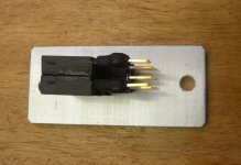
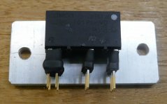
That is why I wanted you to measure it before connecting it to the EXT_IO at the BIII, so you would not apply a voltage when you should not. I have never worked with the selection switch, so I had now way of knowing that Pin 6 & 8 only go LOW or Break the connection. I did also expect them to go HIGH at a certain point. Sorry I told you to buy the level converterIv'e done a bit of testing on the switch unit, I connected a voltage source to the power inputs of the switch module & then read the output pins that go to pin 6 & 8 on the BIII.
I expected to see the output pins vary from High to Low, I tested between the power ground & the output pins. The pins go low to ground but at no stage does a voltage show on the output pins, the reading I got went like this.
Input 1 No reading & No reading
Input 2 To Ground & No Reading
Input 3 No Reading & To Ground
Input 4 To Ground & To Ground
I haven't had a chance to test the BIII inputs
, but you'll need it anyway when you are going for the HiFiDUINO approach. To set a pin to an Input: pinMode(pinNumber, INPUT); (where pinNumber is the number of the pin you want to use)I have no idea how to change an Input to a Output mid code, I thought they where either set as one or the other in the void setup and then left that way.
I am a carpenter so I can read plans, not schematics
Set it to an output: pinMode(pinNumber, OUTPUT);
You already know how to set the pins HIGH or LOW
That is why I wanted you to measure it before connecting it to the EXT_IO at the BIII, so you would not apply a voltage when you should not. I have never worked with the selection switch, so I had now way of knowing that Pin 6 & 8 only go LOW or Break the connection. I did also expect them to go HIGH at a certain point. Sorry I told you to buy the level converter
To set a pin to an Input: pinMode(pinNumber, INPUT); (where pinNumber is the number of the pin you want to use)
Set it to an output: pinMode(pinNumber, OUTPUT);
You already know how to set the pins HIGH or LOW
Your assistance has been all good, I should have followed your instructions more carefully.
Thanks
Everytime you power cycle the DAC it will reset. That is a strange behavior. There is no way to combine the inputs unless you tell the microprocessor to combine the inputs. Check the other switches especially switch 8 of SW2
Thanks for the help, I will get reading.
Hi all,
So I started testing the regulators feeding CCS 5,.25V
i have 2 that measure between 3.290 and 3.295
i have 1 that measures about 1.19
on the other avcc reg, the D1 does not light up but both output measure about 3.42
Do you think I'm good to power the board?
What does D1 indicate?
So I started testing the regulators feeding CCS 5,.25V
i have 2 that measure between 3.290 and 3.295
i have 1 that measures about 1.19
on the other avcc reg, the D1 does not light up but both output measure about 3.42
Do you think I'm good to power the board?
What does D1 indicate?
Success
Glt & Corpius
Thanks again for your help I have installed the relays that I had sitting around doing nothing & now everything works. I can switch between the the sources (must buy more sources or build some sources) and I am back to the SPDIF Coaxial which appears to be working fine, unlike the toslink.
All that's left to implement is the screen.
I am a bit disappointed with the TP people they had 14 days to offer some advice & didn't even though I asked them directly, then within 2hrs of me suggesting the number of dropouts with the BIII was a bit flaky, I had a response from Russ defending the BIII!
Glt & Corpius
Thanks again for your help I have installed the relays that I had sitting around doing nothing & now everything works. I can switch between the the sources (must buy more sources or build some sources
) and I am back to the SPDIF Coaxial which appears to be working fine, unlike the toslink.All that's left to implement is the screen.
I am a bit disappointed with the TP people they had 14 days to offer some advice & didn't even though I asked them directly, then within 2hrs of me suggesting the number of dropouts with the BIII was a bit flaky, I had a response from Russ defending the BIII!
Attachments
Glt & Corpius
Thanks again for your help I have installed the relays that I had sitting around doing nothing & now everything works. I can switch between the the sources (must buy more sources or build some sources
All that's left to implement is the screen.
I am a bit disappointed with the TP people they had 14 days to offer some advice & didn't even though I asked them directly, then within 2hrs of me suggesting the number of dropouts with the BIII was a bit flaky, I had a response from Russ defending the BIII!
I don't use Arduino so why would you want advice from me on that? I knew the arduino community would pitch in.
I figured it was best to allow users who use it to answer your questions. The rest of the details you needed you had in the integration guide.
Last edited:
Iv'e done a bit of testing on the switch unit, I connected a voltage source to the power inputs of the switch module & then read the output pins that go to pin 6 & 8 on the BIII.
I expected to see the output pins vary from High to Low, I tested between the power ground & the output pins. The pins go low to ground but at no stage does a voltage show on the output pins, the reading I got went like this.
Input 1 No reading & No reading
Input 2 To Ground & No Reading
Input 3 No Reading & To Ground
Input 4 To Ground & To Ground
I haven't had a chance to test the BIII inputs
You have to make sure pin 6 and 8 are pulled up. (say with 10K) That is normally done by the controller. With a stock B3 this is done by the on-board controller. You your case you need to be sure *your* controller does the same thing, or do it externally.
Last edited:
Hi all,
So I started testing the regulators feeding CCS 5,.25V
i have 2 that measure between 3.290 and 3.295
i have 1 that measures about 1.19
on the other avcc reg, the D1 does not light up but both output measure about 3.42
Do you think I'm good to power the board?
What does D1 indicate?
D1 definitely should light up. Have you tried testing the AVCC module in isolation?
Last edited:
As for the TOSLINK module - you may need to check that you are getting a good signal out of it. If you have the voltage divider working correctly the output should be equivalent to the consumer level signals.
Also make sure that since you are using the voltage divider you terminate the SPDIF-4 input you are using for that signal at 75R just like the other consumer level inputs.
Also make sure that since you are using the voltage divider you terminate the SPDIF-4 input you are using for that signal at 75R just like the other consumer level inputs.
Thanks. The spdif input for the sabre32 should be rock solid. One idea is to directly connect the toslink output to the input of the BIII and avoid all the "unnecessary" level conversion. One way to do this is to tap the ribbon cable. Another way is to solder to the pins at the bottom of the pin header
Good to read that you have worked it out!
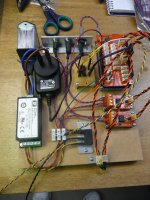
I noticed your tinkerkit MOSFET modules. What are you switching with these modules?
I am switching on my Linkwitz ASP crossovers, that I use for my own speakers, that was a learning experience
There is also a Tinkerkit relay module you cannot see.
I am also switching my 2 amps & the BIII, all sequenced to avoid those awful noises, although I'll have to say the ASP's & BIII dont make really bad noises when switched off before amps, the MiniDSP I was using for the crossover made TERRIBLE noises come through the speakers if you got out of sequence. I remember one day accidentally switching off the MiniDSP first, the noise scared me SO MUCH, while my finger was still on the switch I switched it twice more, needed a good lay down after that
I imagine I may need help with the volume display as I'm not sure howI am going to make it work without removing the firmware chip.
Thanks again.
I have tested in isolation with 5.25V salas shunt input
I have 2 BIII on the standby for dual mono and both avcc D1's did not light up.
I gave the salas a bit more current and both light up now. I should be good to go with those voltages.
thanks.
I have 2 BIII on the standby for dual mono and both avcc D1's did not light up.
I gave the salas a bit more current and both light up now. I should be good to go with those voltages.
thanks.
D1 definitely should light up. Have you tried testing the AVCC module in isolation?
Last edited:
- Status
- This old topic is closed. If you want to reopen this topic, contact a moderator using the "Report Post" button.
- Home
- More Vendors...
- Twisted Pear
- Buffalo III - flexibility without compromise.