Hi Russ,
What is the CMRR of Legato? (If I remember, for IVY it was limited by resistor matching being 60 db with .1% matching)
Hmmm lets clarify the two things.
First 60db would be the worst case for IVY-III with .1%. It would be more accurate to cite a range.
Next legato is not a differential amp, no global feedback so it is not appropriate to compare it to IVY-III in that regard.
Legato is simply an I/V stage (actually 2 pair of independent non-inverting I/V stages) output is essentially the same as the input just converted from current to voltage. Pretty much exactly what you would get with a plain resistor at the output pins to GND - only the output of the DAC does not modulate to the same degree because of the low impedance. As with the simple resistor it will come down to the output levels/value matching. If there is a slight mismatch there will be some differential error given a common mode signal. So essentially any common mode signal is still there at the balanced outputs. But that's what's wonderful about balanced signals, it does not matter in the least. On IVY-III the output common mode is dictated in large part by the device. That is why it is not a straight up comparison.
Where CMRR would come into play to a larger degree is at the BAL/SE stage. I will leave it to you for homework to figure out what the CMRR of that would be. I have never bothered to figure the exact value out for myself. It would depend to some degree on the parts chosen.
")
One nice thing is because most of the common mode noise on the ES9018 is extremely high frequency (far above audible) the passive filters actually get rid of almost all of it before it can really come into play. So practically the "CMRR" (if you want to call it that) is superb.
That's why its important to have those low pass filters. Even if there is a small error between the balanced halves those very high frequencies in play would have been filtered out.Cheers!
Russ
Last edited:
Russ,
Thanks for the clarification. My question was motivated from the previous question. A practical observation (at least for me) is that for IVY, you could afford to be flexible in location and wiring. For Legato, it is important to care about location and wiring, so the best is to put it right under the Buffalo.
Yeah, I know there is cmr on the bal-se conversion, but with IVY there is additional cmr at the inputs of the balanced amp. But if you are feeding a balanced amp (itself having cmr) then you "loose" the additional cmr of IVY if you use Legato (which I plan to use). I am sure all of this is probably inaudible, but it looks good on paper
Last edited:
Good point.
Yes I would agree with that, but the slightly mitigating factor is the balanced signal and low impedance involved. The nice thing about a low impedance is it is somewhat more immune to picking up outside noise, but not much in this particular case. So I would *ALWAYS* use the shortest length you can can practically do.
Yes I would agree with that, but the slightly mitigating factor is the balanced signal and low impedance involved. The nice thing about a low impedance is it is somewhat more immune to picking up outside noise, but not much in this particular case. So I would *ALWAYS* use the shortest length you can can practically do.
Last edited:
But if you are feeding a balanced amp (itself having cmr) then you "loose" the additional cmr of IVY if you use Legato (which I plan to use). I am sure all of this is probably inaudible, but it looks good on paper
That is why the best approach is to eliminate (filter out) any common mode signal you can (other than DC sometimes).
Yes is you use only a single end of the DAC output you will be throwing away quite a lot of what gives it incredible dynamic range. But you can do it if you like, just remember the DC offset so you will need an AC coupling cap.
In that case ,i am consider to get IVY-III stage.
Hi,
I am thinking getting a buffalo3 but I do not have ess9018 datasheet and wonder if this DAC PCM inputs are 5v tolerant ? because I intend to feed that board from a wavefront optorec chip (al1402g = 8channel 24bit receiver chip= Alesis ADAT) which has 5v TTL level outputs. Also can I easily configure this buffalo3 in a 24bit standart right justified PCM mode (bitclock being 64fs = same mode as PCM1794A has) ?
Thanks a lot in advance
It should work just fine (though i have not tried it exactly like you say). This would not be dual mono, but would be stereo with 8 DACs in parallel.
I would say give it try if you feel like it.
Just keep in mind power requirements and the fact that your I/V stage will have double the output swing unless you adjust it.
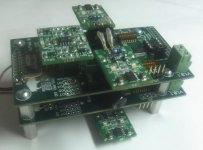
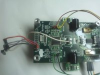
Being encouraged by Russ' comment, I tried the stacking of two BIII boards.
Its joint mechanism is similar to that adopted in IVY III board.
Naturally, I could get the doubled output and I felt more sonic energy. I can't say anything, however, about the improvement of SNR.
The draw of + 5.5 V in total is 0.74 A!
Attachments
Looks very nice, indeed!
What IV converter did you use when you tested with doubled output?
BTW,
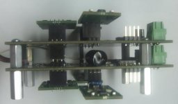
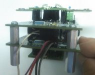
what is that black "thing" in the middle?
/S
What IV converter did you use when you tested with doubled output?
BTW,
what is that black "thing" in the middle?
/S
Being encouraged by Russ' comment, I tried the stacking of two BIII boards.
Its joint mechanism is similar to that adopted in IVY III board.
Naturally, I could get the doubled output and I felt more sonic energy. I can't say anything, however, about the improvement of SNR.
The draw of + 5.5 V in total is 0.74 A!
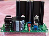
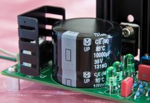
I have build Placid HD that can deliver 800mA at 5.25V. Those components has to be changed in order to get that current safely: both heatsinks to 2.5" high, R2, R2 resistors to 2W and add TO-220 heatsink to A1 bridge. Without heatsink the bridge is too hot (57C). With added heatsink temperature on the bridge is around 43C at 800mA load and 22C ambient.
At 800mA load QN1 heatsink is around 48C hot and QN2 34C. I tried this configuration with 1A load but heatsink is getting too hot for my taste at 58C. You can't get higher heatsink than 2.5" to fit the board, so I set the limit at 800mA. For this test I have used Amveco 70060 2x7VAC 25VA transformer. With 2x9VAC transformer temperature on heatsinks will rise more. With this transformer I got 9.15VDC on C1 with 149mVAC ripple at 800mA. On the load ripple is only 4.6mVAC at 5.25VDC which is good in my book.
Heatsink for the bridge doesn't require any screws. It fits perfectly between AC_IN connector and bridge. You will need to add some thermal compound however. See pictures for details and have fun.
George
Attachments
Nice work! That's a lot of current. the 7V transformer is close to ideal.
I wonder if the 2W R1/R2 resistors really need to be 2W. According to my quick calculations they should only see about .64W max.
One thing to note, is that if you want the CCS to be a bit stiffer you can use a larger value resistor at R1 (R2 remains 1R or less) and a higher voltage reference, but then you will definitely need higher power handling resistors. I had very good success with 4.7R.
the 7V transformer is close to ideal.I wonder if the 2W R1/R2 resistors really need to be 2W. According to my quick calculations they should only see about .64W max.
One thing to note, is that if you want the CCS to be a bit stiffer you can use a larger value resistor at R1 (R2 remains 1R or less) and a higher voltage reference, but then you will definitely need higher power handling resistors. I had very good success with 4.7R.
One other thing - your reported ripple at the load is much higher than it should be for some reason. How did you measure? I just cranked one up to 800ma with a 7.5VAC trafo and I too get about 80-120mvac (I varied current from 600ma to 800ma) ripple at the cap, but I get nothing measurable with my (well up to this point seemingly) excellent DMM at the load (which is drawing about 550ma). Not even a 100th of a millivolt showing. I just confirmed with the scope there there is virtually nothing there between 1 and 1mhz. Perhaps you are not shunting quite enough current, or you are shunting too much (which is very possible)?
Perhaps you are not shunting quite enough current, or you are shunting too much (which is very possible)?
Last edited:
Russ,
I know that at 800mA you can get away with 1W R1 and R2 resistors but they are very hot. I have measured the ripple at C1 an on the load using Agilent U3401A multimeter. However, an internal frequency meter in not showing anything at the output so I am not sure what is that. Unfortunately, I have no scope to verify what is exactly I am measuring here, 120Hz or some HF noise. I have about 20" wires going to the load plus even longer measuring leads so maybe I am picking some other noise than actual ripple. I will try later with different current settings to see if it makes any difference, ether way I am not too concerned about it.
George
What IV converter did you use when you tested with doubled output?
what is that black "thing" in the middle?
In my case, I usually use no active IV converter. Instead, a direct connection of earphones (minimum impedance is about 5 ohm) or line transformers. Wires for those are bound to pins in the first floor DAC board.
The black parts are my standard decoupling capacitors, copper foil & polyphenylene sulfide (PPS) film capacitors.
I2S input and analog output wires are respectively shared by two boards at the pins that bridge the first and the second floor boards.
Attachments
- Status
- This old topic is closed. If you want to reopen this topic, contact a moderator using the "Report Post" button.
- Home
- More Vendors...
- Twisted Pear
- Buffalo III - flexibility without compromise.