It says this module runs 12-15v, and that 15v is the "best".
Is it anyway possible to make it run even higher voltage, say 18v? and would there be any benefit doing that? (i'm just thinking it wouldn't be necessary burning 9v in the shunt-PSU i have right now, which is why i ask)
Is it anyway possible to make it run even higher voltage, say 18v? and would there be any benefit doing that? (i'm just thinking it wouldn't be necessary burning 9v in the shunt-PSU i have right now, which is why i ask)
Is it possible to use other resistors around the opamp to get some gain there ? Change the resistors 21-24 to 10 kohm ?
Yes. It's a straight forward op-amp stage, so the usual gain calculations can be used.
Greetings again.
I tried the opamp in an O2 and it confirms to be functionning. I am powering legato3 with salas bib with about 300ma on each +- 15 V rails. The bal section can be trimmed to offset 0 v dc. The SE section cannot be trimmed no matter what direction the wiper on vr3 vr4 are turned. I'm not using the buffer section so I jumpered j5,j6. I don't have anything populated at r25, r26, l1,L2 uc2,uc3.
ANy help would be appreciated.
Note: my system is direct with no caps so I don't want to try it out live before knowing if there is DC at the SE end
By the way, how sensitive is the legato for Input voltage difference between the positive and negative voltage? I'm going for resistor to set voltage, not pots and wonder if it would be +14.90/-15.00 would that just be trimmed out at the output?
And also as said, if i wire the outputs to my linestage without any ground connection, would that be any problem (they are in same case, and i don't want to mix ground from both supplies, but they will all be connected to chassis through a resistor or rectifier bridge)?
And also as said, if i wire the outputs to my linestage without any ground connection, would that be any problem (they are in same case, and i don't want to mix ground from both supplies, but they will all be connected to chassis through a resistor or rectifier bridge)?
Toslink problem with Buffalo

Sorry for posting it here. I could not find the Buffalo tread. On your support side I can not post pictures like this. The toslink make the lock led flashing. I use the 270 series resistor and 100 ohm parrallel. Will it make the difference with 75 ohm ? Or do I have to change anything else ?
Sorry for posting it here. I could not find the Buffalo tread. On your support side I can not post pictures like this. The toslink make the lock led flashing. I use the 270 series resistor and 100 ohm parrallel. Will it make the difference with 75 ohm ? Or do I have to change anything else ?
Last edited:
View attachment 326457
Sorry for posting it here. I could not find the Buffalo tread. On your support side I can not post pictures like this. The toslink make the lock led flashing. I use the 270 series resistor and 100 ohm parrallel. Will it make the difference with 75 ohm ? Or do I have to change anything else ?
Reduce the size of the picture and post it on the support forum please.
This is definitely not the right thread.
")
Still one hint, try tying -IN to GND for that input.
Do not respond in this thread or I will start deleting posts.

Thanks!
Russ
It could be your PS settling? Its hard to say. if you like open up a thread on the support forum with pictures.
Thanks for your reply ,
I think it is time warm up of Mosfet and Transistor ?.
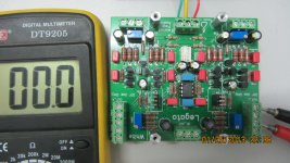
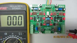
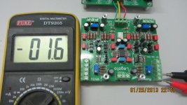
I measured all out put is 0V with 200mV DC meter, then I off/on power,the output about 8mV and measured -1.6mV in 5 minute later .
It is normal ? .Can I connect direct to tube pre-amplifier ? .
Van Duy
Attachments
Last edited:
It really depends on the amp.
BTW when measured like that the inputs are floating. Which will effect things.
This is why you need to measure again once the DAC is conneted.
If the few mv of warm-up offset is too much your amp then use AC coupling caps.
One other note - the main pair of NPN (QN5 QN6 etc) can be thermally coupled. This should significantly reduce any such drift.
I do this by gluing them together or using heat-shrink tubing etc.
Cheers!
Russ
One other note - the main pair of NPN (QN5 QN6 etc) can be thermally coupled. This should significantly reduce any such drift.
One picture = 1000' of words.
This if from an earlier Legato but the picture is principal.
Sorry for interrupting the threat.
Attachments
- Status
- This old topic is closed. If you want to reopen this topic, contact a moderator using the "Report Post" button.
- Home
- More Vendors...
- Twisted Pear
- Legato 3 - Look ma! No caps!