You are welcome!
When I look at the spectrum of the MicroCap10 simulation I did on
the buffered and buffer-less Legato 1, I see that 3H (60k) is
about the same at -116dB for both the 75m and 50mA currents..
So, maybe you missed this?
/IR
When I look at the spectrum of the MicroCap10 simulation I did on
the buffered and buffer-less Legato 1, I see that 3H (60k) is
about the same at -116dB for both the 75m and 50mA currents..
So, maybe you missed this?
/IR
Hi IngemarR
First thanks for Your simulations...
I have to say that thanks to Your and Russ input this simple thread did turn into "new dimention"...definetely much more interesting...
Legato now has many incarnations .....
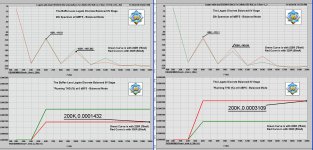
But I have been looking at Your Buffer Less Legato 1 simulation and comparing to Legato1 with Buffer and THD for 3H - at 60kHz changed from -110dB to -116,9 dB .. and totall THD from 0,0003109 to 0,0001432 and this could explain why Russ is telling that when not needed it is better to go without Buffer....
But why this change is only at 50mA CCS standing current, R=330 RED Line?? and almoust nothing or even worst resoults for 75mA, R=220 Green Line..?? . Any possible explanation ... Or do I miss something..?
For both sim I/V R is 75Ohm...
Rosendorfer
A BJT instead of a MOSFET could have 10X more Gm, so, Russ,
I am even more curious now. Capacitances are higher in MOSFETs as far as I know...hmmm....
It would be most apprecitaed if you could tell me what this "deeper" is?
/IR
It is more about the way the two devices work together. Really we are creating a compound device (CFP with a driving BJT and a MOSFET heavy lifter) that behaves as one. I won't completely spoil the ending because I want to leave some mysteries for the reader to solve on their own.
One hint though. Look at what happens to the local CFP feedback when you can raise the CFP resistor to 1K without losing any collector current through that BJT driver... Wow that CFP sure does look a lot more linear now! Really just like it were an ultra high beta BJT!!! Why? Well because we are making the whole thing look more and more like a well really well biased BJT. This is a case where the gate threshold voltage of the MOSFET works to or advantage! We got more gain at the same collector current(1K CFP R for MOSFET, 392 for BJT). Nice.
")
Now some my still ask even after the above explaination: Ok Russ, but why not just use 1K with the BJT? Well the answer is simple. That resistor sets the current through the BJT driver. If that current is too low (which at less than half the voltage drop it will be) you are now not using the BJT to its full potential, and what is more, you lose a good deal of local feedback.
Ok I did not leave much for you to figure out. Consider it an early Christmas present.
There is one further point. The FETs fundamental behavior as a voltage controlled resistor also very likely comes into play. The capacitance at the gate will also always be swamped by the heavy bias and does not really come into play at the frequencies we are working at.
Cheers!
Russ
Last edited:
When I say that your measurements include BOTH distorsion from the ESS9018 (Buffalo 2) and the Legato 1, am I then correct?
Did you use the buffer on the Legato 1?
/IR
Hi IngemarR
Yes You are of cause right I even would say that my measurments include even more of distortion sources .. and I would say that probably Buffalo is not the main one.. that's why I was realy suprised that even with this far from beeing perfect measurment setup I could see the effect ....
And Yes the buffers have been used....
That's why I asked about symulations without the buffer...as I wonder if they play any sygnificant role in generating THD...
You are welcome!
When I look at the spectrum of the MicroCap10 simulation I did on
the buffered and buffer-less Legato 1, I see that 3H (60k) is
about the same at -116dB for both the 75m and 50mA currents..
So, maybe you missed this?
/IR
Well I'm confused....
Please have a look at attached screens from Your measurments, I'm refering to......
There is ...3H (60k)/ -110.1dB - Red line 330R 50mA @ Legato buffered ..
Rosendorfer
Attachments
Let's go to email.
/IR
/IR
Hi IngemarR
Yes You are of cause right I even would say that my measurments include even more of distortion sources .. and I would say that probably Buffalo is not the main one.. that's why I was realy suprised that even with this far from beeing perfect measurment setup I could see the effect ....
And Yes the buffers have been used....
That's why I asked about symulations without the buffer...as I wonder if they play any sygnificant role in generating THD...
Well I'm confused....
Please have a look at attached screens from Your measurments, I'm refering to......
There is ...3H (60k)/ -110.1dB - Red line 330R 50mA @ Legato buffered ..
Rosendorfer
The result is not at all unexpected for me, it is likely the BAL/SE stage that you are really seeing.
You would need to omit the BAL/SE stage and measure the balanced output directly to see how the I/V stage itself is doing. That would be a better match for the simulation.
The THD with or without the buffer is pretty much identical as long as the load is > 2K or so.
The THD with or without the buffer is pretty much identical as long as the load is > 2K or so.
Hi Russ
As for regular Stereo Mode Buffalo-Legato system, simulations shows THD -125dB And this is more than Perfect /Excellent results....
But FOR MY DUAL BUFFALO SETUP...with 32mA Legato Input current!!!
As far as IngemerR simulations go The THD with or without the buffer are different .....Exactly as -110,1dB and -116dB
for CCS 50mA/R330, I/VR=75 !!
So this is just some learning process in here with my "special case" involved...
Rosendorfer
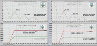
I know understand what Rosendorfer is asking, and after redoing the simulation, I see that I have reversed the colours for 75mA and 50mA for the Buffer-Less Legato 1 fed by dual ESS9018:s.
My apologies.
The attached image is a correct one.
My apologies.
The attached image is a correct one.
Hi IngemarR
Yes You are of cause right I even would say that my measurments include even more of distortion sources .. and I would say that probably Buffalo is not the main one.. that's why I was realy suprised that even with this far from beeing perfect measurment setup I could see the effect ....
And Yes the buffers have been used....
That's why I asked about symulations without the buffer...as I wonder if they play any sygnificant role in generating THD...
Well I'm confused....
Please have a look at attached screens from Your measurments, I'm refering to......
There is ...3H (60k)/ -110.1dB - Red line 330R 50mA @ Legato buffered ..
Rosendorfer
Attachments

The THD with or without the buffer is pretty much identical as long as the load is > 2K or so.
OK then I have to say this:...
Russ knows what he is saying...
Now this is what we can call "prety much identical".........

Rosendorfer
Attachments
I used 1MEG as load.
/IR
/IR
OK then I have to say this:...
Russ knows what he is saying...
Now this is what we can call "prety much identical".........
Rosendorfer
Thanks for the Xmas gift, Russ!
I think it is the most hard-to-open-present I have ever received
/IR
I think it is the most hard-to-open-present I have ever received
/IR
It is more about the way the two devices work together. Really we are creating a compound device (CFP with a driving BJT and a MOSFET heavy lifter) that behaves as one. I won't completely spoil the ending because I want to leave some mysteries for the reader to solve on their own.
One hint though. Look at what happens to the local CFP feedback when you can raise the CFP resistor to 1K without losing any collector current through that BJT driver... Wow that CFP sure does look a lot more linear now! Really just like it were an ultra high beta BJT!!! Why? Well because we are making the whole thing look more and more like a well really well biased BJT. This is a case where the gate threshold voltage of the MOSFET works to or advantage! We got more gain at the same collector current(1K CFP R for MOSFET, 392 for BJT). Nice.
Now some my still ask even after the above explaination: Ok Russ, but why not just use 1K with the BJT? Well the answer is simple. That resistor sets the current through the BJT driver. If that current is too low (which at less than half the voltage drop it will be) you are now not using the BJT to its full potential, and what is more, you lose a good deal of local feedback.
Ok I did not leave much for you to figure out. Consider it an early Christmas present.
There is one further point. The FETs fundamental behavior as a voltage controlled resistor also very likely comes into play. The capacitance at the gate will also always be swamped by the heavy bias and does not really come into play at the frequencies we are working at.
Cheers!
Russ
Which Ludahl transformers are you using?
Thanks
JD
Thanks
JD
Hi
As for transformer Yes I use it for balanced to SE conversion.
Well I'm not saying that this is the best solution but not having any Opamp was very tempting .specilaly after using IVY for some time....
As for power at the moment I do have one PS for Legato, but I'm working on that..
Best Regards
Rosendorfer
Thanks,
and which I/V resitors have you decided to use? (with the transformers)
JD
and which I/V resitors have you decided to use? (with the transformers)
JD
Hi JD
I heave been using Lundahl LL1517 trafo.
This is probably not perfect one for this application, but this is one I have...
Actually since last month I'm using LME op-amp as dif 2 SE for time being and working on something else to use as dif 2 SE...
Rosendorfer
Thanks,
and which I/V resitors have you decided to use? (with the transformers)
JD
Hi JD
I use standard Legato Resistor values, no changes there...
Well of cause some resistor changes could be beneficial as it looks from IngemarR and Russ simulation but please remember that this is with 0dB signall.
I'm using Volumite and almoust never volume is full scale up...@0dB this is almoust never the case....
But ...If You're using Volume control not at Buffalo but after Legato then some changes could be beneficial....
Rosendorfer
Russ please help
Dear Russ,
when you say what below you intend to connect after the 100uF caps or before?
I mean: do you intend to use the 4 caps or not?
The reason I ask is because I want to use BAL/SE without caps and put a small cap only on the SE out.
SO parallel 2 and 2 output without caps --> go into BAL/SE --> put 1-2uF cap (if the offset is not high --> PRE
Thanks in advance!
GM
Not sure I follow what would be scary.
You would connect the same phase from one side of the legato to the other. You just have to keep in mind that they are inverted so the + on one side would connect to the - on the other.
I will try to draw a picture when I get a chance.
One benefit is you get half the output impedance.
- Status
- This old topic is closed. If you want to reopen this topic, contact a moderator using the "Report Post" button.
- Home
- More Vendors...
- Twisted Pear
- Buffallo Dual Mono 1 Legato