Got a bit confused now:But, since my line-stage is balanced with 5,4dB gain on each phase - then wouldn't it be better to connect output from each phase with a 2.7R resistor to GND, then maybe the cap between both phases (what does this do in this specific case?) and then into the step-up transformer.
In my case the output from the transformer would go straight into the volume attenuator (50k R2-R log attenuator between the phases not down to GND) with approx 15cm wire, twisted and then maybe 15cm wire into my tube-line-stage.
Thare shouldn't be any trouble running from the step-up into the volume right? since impedance matching seems quite fine ~1.85k into 50k.
Also Joe, wouldn't it be better skipping the GND connection on the output, at least when i run transformer - to keep DAC-GND from my Line-stage GND?
Thanks alot for taking your time helping in this thread so far")
Output of buffalo is loaded with either 2pc of 2.7Ohm or one 2.7Ohm wire with ground in the middle into the transformer, yes?
This is the best way, linestage not involved in the 2.7Ohms?!
Because the secondary is always floating, you can choose what to do.
How have you come to 1.85k with the Lundahl?
Did you already check if the Lundahl can do it?
Output would be loaded with 2 x 2.7R resistors (one for each phase), and GND in between them.
How i come up to approx 1.85K impedance is because i have calculated it.
LL1933 should work according to Lundahl (up to 50mA) and does have primary impedance of 0.8R per winding, and 85R on secondary.
So on the primary side i have 5,4R + transformer 1,6R. Transformer ratio of 1:16 equals 256x impedance ratio. so 7x256 = 1792ohms plus the impedance from the secondary 85/2=42,5R (since they are paralelled) so in total 1834,5R simple as that.
What i may have done wrong with the above calculations is that i'm not shure if the the loading resistors would "seem" in paralell for looking from the secondary of the transformer. If it would be that way, then impedance would only be 938,5R.
Anybody that can calarify this?
Also one last thing, would it be better having the primary floating (center tap not connected to GND) or would it be better to connect it straight to ground?
Also, when running outputs directly from dac to transformer, wouldn't there be any issues with DC-offset? i'm just thinking if coupling cap would be needed for transformers that cannot take DC?
Output would be loaded with 2 x 2.7R resistors (one for each phase), and GND in between them.
How i come up to approx 1.85K impedance is because i have calculated it.
LL1933 should work according to Lundahl (up to 50mA) and does have primary impedance of 0.8R per winding, and 85R on secondary.
So on the primary side i have 5,4R + transformer 1,6R. Transformer ratio of 1:16 equals 256x impedance ratio. so 7x256 = 1792ohms plus the impedance from the secondary 85/2=42,5R (since they are paralelled) so in total 1834,5R simple as that.
What i may have done wrong with the above calculations is that i'm not shure if the the loading resistors would "seem" in paralell for looking from the secondary of the transformer. If it would be that way, then impedance would only be 938,5R.
Anybody that can calarify this?
1.6 Ohm are primary dc resistance, it does not play a role here, because important are the inductance and reflected secondary load.
If you have a normal loading resistor of 47k, it would reflect (47k :256) about 200Ohms, parallel to your 5.4 Ohms, no problem here.
Also one last thing, would it be better having the primary floating (center tap not connected to GND) or would it be better to connect it straight to ground?
It would be helpful if you carefully read my post 372!
That was the main reason I wrote the post.
Also, when running outputs directly from dac to transformer, wouldn't there be any issues with DC-offset? i'm just thinking if coupling cap would be needed for transformers that cannot take DC?
Definitely not, had been discussed as well.
I would like to thank Joe Rasmussen.
Thanks.
It is a pity that The Sabre chip sounds o.k. even in voltage mod, so often people use 1.1 trannies, which is still much better than most of the active I/V stages, but sounds just broken compared to (nearly) passive current mode, but there are people paying 1000 Dollars for a transformer to run a Sabre in voltage mode....
Yep.
Whether using step-up or 1:1 Txs, that Z on the Primary needs to be as low as possible - and it benefits BOTH the DAC and Txs. But in your case, step-up makes it even more important as I see it.
I suspect that using a step-up transformer with 1K on the Primary is not so good because the source Z of the DAC is way too high into the Primary. In that case a step-up transformer would indeed sound "broken" - so the Lo Z is also good for step-up transformers as the need that Lo Z on the Primary may be even greater with step-ups. And that Z can be lower than 1:1 - so do it.
It really doesn't matter what the Tx post-DAC solution is (if using Txs), the basic rule is the same. Get the Z on the Primary as low as possible, and don't worry about grounding the Sabre DAC - and that passive I/V is the way to go, even partially loading down 1:1 Txs. It just comes down to whether you have enough output.
Even with non-Tx solution, Lo Z passive I/V is the way to go. But here the benefit is only to the DAC and very important too. But using Txs, they should always sound better with Lo Z on the Primary.
Hope I haven't sounded to repititious.
Cheers, Joe
According to Lundahl at least does the transformer resistance count into total impedance, and logically i do not see why it wouldn't?
Anyway, have i understand right that from the beginning you just had a 1,2R "resistor/wire" between the positive and negative phases, and then you split it connecting the "middle" to the transformer Center Tap? but you did never connect to DAC-GND?
Which of these solutions did you use?
Joe: did you see my questions at post #380
Anyway, have i understand right that from the beginning you just had a 1,2R "resistor/wire" between the positive and negative phases, and then you split it connecting the "middle" to the transformer Center Tap? but you did never connect to DAC-GND?
Which of these solutions did you use?
An externally hosted image should be here but it was not working when we last tested it.
Joe: did you see my questions at post #380
Last edited:
According to Lundahl at least does the transformer resistance count into total impedance, and logically i do not see why it wouldn't?
Anyway, have i understand right that from the beginning you just had a 1,2R "resistor/wire" between the positive and negative phases, and then you split it connecting the "middle" to the transformer Center Tap? but you did never connect to DAC-GND?
Which of these solutions did you use?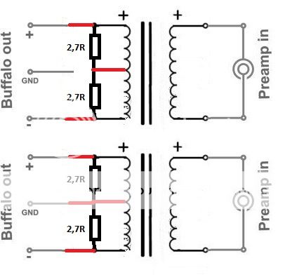
Joe: did you see my questions at post #380
No, both are not good. The second is worst as you will get DC through transformer.
Only connect the Ground to the centre of where the resistors meet.
Connect nothing to the transformer's centre tap.
You do not want any potential DC to go through the transformer - the DC resistance of the Primary (or any part of it) must not be in parallel with the resistors, or else some DC current will flow through that part of the Primary. You was all the DC current to go through the resistors, to ground.
If the two resistors are well matched, then both extremities of the Primary will sit at the same voltage. That means no DC current through the Primary of the transformer.
Is that clear enough?
Re Secondary. In theory, best not to be grounded. Especially not grounded when balanced used in balanced mode. If unbalanced, then still best to let it float at the transformer end (if possible or practical) and ground at the receiving end, whether that be a pot/volume control or not. That way you get "galvanic isolation" - that is that the ground of the DAC is isolated from the ground of the preamp or whatever is at the receiving end. Isolating grounds are good in principle.
Cheers, Joe
Last edited:
Only connect the Ground to the centre of where the resistors meet.
Connect nothing to the transformer's centre tap.
You do not want any potential DC to go through the transformer - the DC resistance of the Primary (or any part of it) must not be in parallel with the resistors, or else some DC current will flow through that part of the Primary. You was all the DC current to go through the resistors.
If the two resistors are well matched, then both extremities of the Primary will sit at the same voltage. That means no DC current through the Primary of the transformer.
Is that clear enough?
Re Secondary. In theory, best not to be grounded. Especially not grounded when balanced used in balanced mode. If unbalanced, then still best to let it float at the transformer end (if possible or practical) and ground at the receiving end, whether that be a pot/volume control or not. That way you get "galvanic isolation" - that is that the ground of the DAC is isolated from the ground of the preamp or whatever is at the receiving end. Isolating grounds are good in principle.
Cheers, Joe
Yes, i think so. Like my second example, but remove the center tap from the middle/gnd between the resistors.
But what is the cap for, the 0.33uF one you had between positive and negative phases?
Also when running primary side this way and you look from the secondary side (1:16). Does the reflected impedance look like (2,7+2,7)x256=1138,4R or (2,7/2)x256=345,6R - that is, do they look like series OR parallel?
But what is the cap for, the 0.33uF
Please note that was a NON-transformer solution. That cap was specific to that circuit and not transformers. The transformer is a bandpass filter and does not need the cap.
Cheers, Joe
Hi Joe, do the resistors need to be terminated to ground? I have bought a Buffalo DAC, haven't assembled it yet but for an IV convertor I was planning on an approach shown in the diagram ie I will feed the DAC output into my Lundahl transformer, and as I prefer not to use a preamp, I will vary level by use of a switched resistor (24 position switch) also across the output - its easier if I can just use a single resistoer across the 2 phases rather than having 2 resistors (which then requires a double pole switch). What do you think?No, both are not good. The second is worst as you will get DC through transformer.
Only connect the Ground to the centre of where the resistors meet.
Connect nothing to the transformer's centre tap.
You do not want any potential DC to go through the transformer - the DC resistance of the Primary (or any part of it) must not be in parallel with the resistors, or else some DC current will flow through that part of the Primary. You was all the DC current to go through the resistors, to ground.
If the two resistors are well matched, then both extremities of the Primary will sit at the same voltage. That means no DC current through the Primary of the transformer.
Is that clear enough?
Re Secondary. In theory, best not to be grounded. Especially not grounded when balanced used in balanced mode. If unbalanced, then still best to let it float at the transformer end (if possible or practical) and ground at the receiving end, whether that be a pot/volume control or not. That way you get "galvanic isolation" - that is that the ground of the DAC is isolated from the ground of the preamp or whatever is at the receiving end. Isolating grounds are good in principle.
Cheers, Joe
Attachments
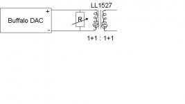
Hi Joe, do the resistors need to be terminated to ground? I have bought a Buffalo DAC
Yes, in my opinion that is what will get you the max results. It does two things, converts DC voltage offset to current offset, and creates the lowest impedance possible (our topic is Txs) into the Primary.
Transformers works at their best when driven from a low impedance. The output impedance of the Sabre DAC is quite high, many times higher than voltage DACs. So the low impedance cannot come from the DAC itself, it in a sense has to come from the Ground. Simple as that. (Current type DACs like B-B does this naturally as the have a very high output Z and relies on Ground to make it low). And Sabre DACs are also at their most linear when seeing a Lo Z current mode. The usual "common garden" solution is to use an opamp with a Virtual Ground approaching Zero Ohm. But this is a feedback trick. Normally with "current" DACs with DC voltage offset, this means that the Zero Ohm has to actually float at the same DC voltage offset of the DAC (usually 1.65V).
But the Sabre DAC is very different beast, it has a fixed output Z of 780 Ohm. Paralleling four phases will give you 195 Ohm combined, eight will give you 97 Ohm. These are all relative high - not good for Txs. But ahh... that output impedance also acts as a current limiter when shortened to ground, and in the Sabre DAC means we can do something we cannot do with any other DAC: Pull it to Ground! The DC offset current is 1.65V/780R = 2.1mA per phase. It cannot go higher than that - so we use that to advantage. We can now construct a near REAL EARTH rather than a Virtual one.
The downside? Only slightly more heat generated by the DAC's outputs and that about 3.5mW phase per side. Negligible. In total about 50mW.
The DC offset current we have created must go through the resistors and not the transformers. The resistors should also be 1% or better matched.
Cheers, Joe
Thanks.
I suspect that using a step-up transformer with 1K on the Primary is not so good because the source Z of the DAC is way too high into the Primary.
Cheers, Joe
Who is the blame? I am using 1.2 Ohm, probably you misread my post??!!
Yes, in my opinion that is what will get you the max results. It does two things, converts DC voltage offset to current offset, and creates the lowest impedance possible (our topic is Txs) into the Primary.
Cheers, Joe
There must be something in this grounding schema, that prevents people from doing/believing it, so they still ask about it.
I have thought about and would explain it this way:
Without grounding the mid point, it is for me like a class B amplifier. There is no current, when there is no sound. More loudness means more current, so the dac bounces between more voltage mode (loudness low) and more current mode (loudness high).
When grounding the midpoint, we have a class a situation, there is always a current flow.
I want to stress again, that the dac in current and hopefully passive mode sounds extremly well and can only be compared to the very best, i.e. Meitner. Best power supply is mandatory, I use LipoFe/NimH cells without any regs.
There must be something in this grounding schema, that prevents people from doing/believing it, so they still ask about it.
When grounding the midpoint, we have a class a situation, there is always a current flow.
.
Hello Rolls !
If there is always current in primary, can use any transformer without gap ?
Untill now, I was using Jensen JT-11-emcf without grounding , with 6 ohms I/V from +- ess9018 output and tube stage 50x gain.
Thanks
rolls means current flow that appears on DAC-resister-GND (not on primary)
Right?
Yes, current can just flow to ground, because there is the same tiny voltage on either side. Very thin wire is the best I/V resistor.
i also want to thank mr. rasmussen! i listened for some months with a s&b tx103, 1:10, 2x 25R to ground. sounded very nice, but last week i changed to 1:5, 2x 1R to ground followed by a choke loaded 5842(130v, 15ma), choke input psu, superreg and i could not believe it. just fantastic)))))
will change the resistors to tx2575, cap to duelund.....nothing will beat this;-)
)))))will change the resistors to tx2575, cap to duelund.....nothing will beat this;-)
There must be something in this grounding schema, that prevents people from doing/believing it, so they still ask about it.
Maybe because this is a trick you can only do with Sabre DAC where you have a DAC with a 'voltage' offset. Try that with any of the other 'voltage' DACs or even 'current' DACs, and you will likely cause near instant damage.
You can do it with 'current' DACs like Burr-Brown 1792,1794,1796 DACs, as these have only a current offset (not a problem to deal with) and no voltage offset (much more tricky) and can be brought straight to Ground anyway.
When grounding the midpoint, we have a class a situation, there is always a current flow.
When you have an output device, whether Fet or BiPolar, if you increase the current or 'bias' you also get higher transconductance and that should improve linearity. This is also a fact in Class A circuits, whether gain stages or buffers. So in this case it affects an internal change within the DAC by pulling out external current (again trading offset voltage to create offset current). But I believe there are a number of factors here, but this is an important one IMO.
Cheers, Joe
i also want to thank mr. rasmussen! i listened for some months with a s&b tx103, 1:10, 2x 25R to ground. sounded very nice, but last week i changed to 1:5, 2x 1R to ground... and i could not believe it. just fantastic
I have been preaching this for near two years, and In think the penny is starting to sink in. I would not want to run the ES9018 any other way, it's needs to be pulled to a literal ground rather than a virtual one using the lowest value possible, as low as you can get away with.
Cheers, Joe
.....using the lowest value possible, as low as you can get away with.
Cheers, Joe
so you think it would make sense to use the transformer in 1:20 and just take a wirewrap wire which would give me around 0,25R with a lenght of about 2,5"?
at least the transformer was made for voltages like this
cheers,klaus
- Status
- This old topic is closed. If you want to reopen this topic, contact a moderator using the "Report Post" button.
- Home
- More Vendors...
- Twisted Pear
- Buffalo II & transformers