What's Sidecar?
It's a BIII accessory:
Sidecar, which is used for switching between S/PDIF inputs and PCM(I2S) or DSD inputs. The module is daisy chained between the S/PDIF receiver (above) and the Buffalo-III. By applying 5VDC to the Trigger header, the relays switch between the S/PDIF inputs and the inputs on the PCM/DSD header, and then to the Buffalo-III. Please note that this module supports only stereo PCM and DSD signals.
")
You can't use Sidecar with BII, that's the reason I bought the BIII
then, that I have to use for Bii?.
If the sidecar is what I need, I can manually apply 5v with a switch. Is that it?
It depends. The added cost of the BIII (and the benefit) lies most of all in the Trident regulators.Is there any real benefit of BIIIs in dual mono vs BIIs?
If you don't have those on the BII, I'd add them. IMO it's a more efficient way of spending money than blindly adding a second DAC.
If you already have the Tridents, it becomes another question. You could strip the Tridents off the BII, and use them on the BIII. This lowers your cost of upgrading. Reinsert the beads and you have a functioning BII you can sell, plus a set of Tridents to use for a single BIII.
BII tube/legato v3
Happy New Year!
I have my project almost over. I have a prototipo mounted in a wooden box. It's a buffalo II DAC with selectable output stage between tube and legato v.3. This change is with a switch. I have used panasonic tq2 relays to make the change.
The relays off (no power) give way to LEGATO. The signal path between dac and legato is 4cm.
The relays on (with power) give way to tube-i-Zator. The signal path is 8-10 cm.
At the moment I have a little more length in the cables and they are somewhat messy, until the final place in the box. All signal cables are silver.
I have used shunt regulators for all power supplies. 2X tridents and a shunt regulator for the clock. Some Russian PIO capacitors and bypass ft3. When placed in the final box I put Mundorf silver in oil in output valves and some resistance Texas Instruments.
The DAC is controlled by arduino. I'm yet to put a usb-i2s interfece. Russ / Brian for when we have the usb-i2s xmos?. At the moment it is connected by toslink. My source is a MacMini.
The sound is fantastic. At the moment I do not find differences with the version without relays
The pictures are made with a mobile phone.
Sorry for my bad English.
A design image for the box and the front. It will be a chassis with 10mm front modu.it
Regards
Al
Happy New Year!
I have my project almost over. I have a prototipo mounted in a wooden box. It's a buffalo II DAC with selectable output stage between tube and legato v.3. This change is with a switch. I have used panasonic tq2 relays to make the change.
The relays off (no power) give way to LEGATO. The signal path between dac and legato is 4cm.
The relays on (with power) give way to tube-i-Zator. The signal path is 8-10 cm.
At the moment I have a little more length in the cables and they are somewhat messy, until the final place in the box. All signal cables are silver.
I have used shunt regulators for all power supplies. 2X tridents and a shunt regulator for the clock. Some Russian PIO capacitors and bypass ft3. When placed in the final box I put Mundorf silver in oil in output valves and some resistance Texas Instruments.
The DAC is controlled by arduino. I'm yet to put a usb-i2s interfece. Russ / Brian for when we have the usb-i2s xmos?. At the moment it is connected by toslink. My source is a MacMini.
The sound is fantastic. At the moment I do not find differences with the version without relays
The pictures are made with a mobile phone.
Sorry for my bad English.
An externally hosted image should be here but it was not working when we last tested it.
An externally hosted image should be here but it was not working when we last tested it.
An externally hosted image should be here but it was not working when we last tested it.
An externally hosted image should be here but it was not working when we last tested it.
A design image for the box and the front. It will be a chassis with 10mm front modu.it
An externally hosted image should be here but it was not working when we last tested it.
Regards
Al
Here is my finished build. No arduino. Atmega16 based controller and the board is my own design. Remote control, Em14 encoder for volume/balance and PWM supplying the LCD backlight for brightness adjustment.
Inside pics can be found from the link. Volume control is not yet implemented in the inside pics as they are so old. Volume knob is attached to the encoder with a 7mm bar going through two ball bearings to get that "high-end feel". Also the encoder was not enough to support the weight of the knob by itself.

http://amattsso.1g.fi/kuvat/Audio/DSC_8643_.jpg/
Inside pics can be found from the link. Volume control is not yet implemented in the inside pics as they are so old. Volume knob is attached to the encoder with a 7mm bar going through two ball bearings to get that "high-end feel". Also the encoder was not enough to support the weight of the knob by itself.
http://amattsso.1g.fi/kuvat/Audio/DSC_8643_.jpg/
Happy New Year!
I have my project almost over. I have a prototipo mounted in a wooden box. It's a buffalo II DAC with selectable output stage between tube and legato v.3. This change is with a switch. I have used panasonic tq2 relays to make the change.
The relays off (no power) give way to LEGATO. The signal path between dac and legato is 4cm.
The relays on (with power) give way to tube-i-Zator. The signal path is 8-10 cm.
At the moment I have a little more length in the cables and they are somewhat messy, until the final place in the box. All signal cables are silver.
I have used shunt regulators for all power supplies. 2X tridents and a shunt regulator for the clock. Some Russian PIO capacitors and bypass ft3. When placed in the final box I put Mundorf silver in oil in output valves and some resistance Texas Instruments.
The DAC is controlled by arduino. I'm yet to put a usb-i2s interfece. Russ / Brian for when we have the usb-i2s xmos?. At the moment it is connected by toslink. My source is a MacMini.
The sound is fantastic. At the moment I do not find differences with the version without relays
The pictures are made with a mobile phone.
Sorry for my bad English.
An externally hosted image should be here but it was not working when we last tested it.
An externally hosted image should be here but it was not working when we last tested it.
An externally hosted image should be here but it was not working when we last tested it.
An externally hosted image should be here but it was not working when we last tested it.
A design image for the box and the front. It will be a chassis with 10mm front modu.it
An externally hosted image should be here but it was not working when we last tested it.
Regards
Al
Interesting! Nice build!
Cheers!
Russ
Here is my finished build. No arduino. Atmega16 based controller and the board is my own design. Remote control, Em14 encoder for volume/balance and PWM supplying the LCD backlight for brightness adjustment.
Inside pics can be found from the link. Volume control is not yet implemented in the inside pics as they are so old. Volume knob is attached to the encoder with a 7mm bar going through two ball bearings to get that "high-end feel". Also the encoder was not enough to support the weight of the knob by itself.
http://amattsso.1g.fi/kuvat/Audio/DSC_8643_.jpg/
Nice build! Very DIY - very cool! I really like the panel.
Thanks. Seems the previous link does not work with the "/" at the end but all the pictures can be found at http://amattsso.1g.fi/kuvat/Audio/
Last edited:
Hello,
I am trying to add a small transformer to the spdif input of the Buffalo II DAC to galvanically isolate it from the spdif source (Squeezebox Touch) which has not the transformer at the output.
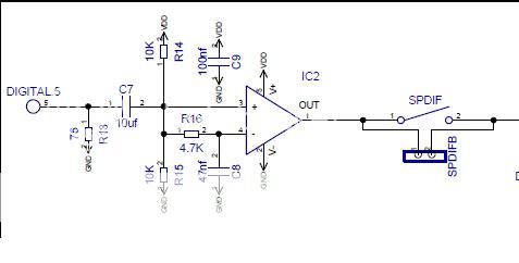
Looked at the schematic of Buffalo I (i don't have the schematic of B II) and we see that at the spdif input there is one R13 75Ohm. This is also probabaly the same in BII.
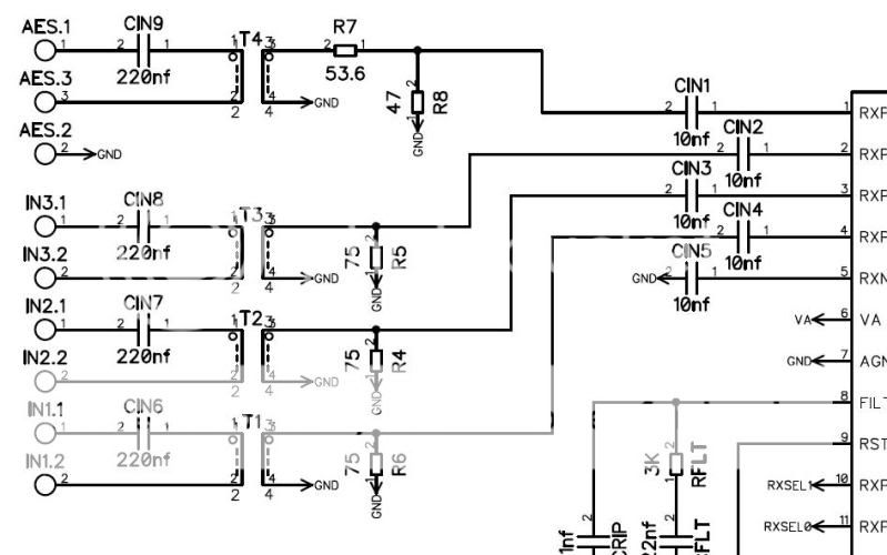
Than i looked at the schematic of the MUX module and we see that at the input there is C8 220nF, than the T3 Newava Transformer S22083.
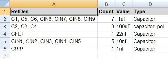
On the schematic CIN6-CIN9 are 220nF, in the Excel Bill of Material CIN6-CIN9 are 0.1uF.
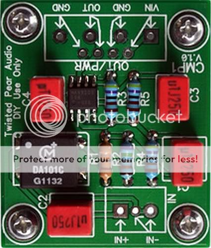
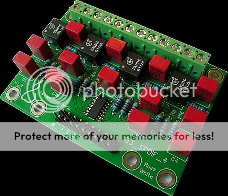
Than i looked at the pictures of the new spdif inputs for Buffalo III and we see at the input 0.1uF and Murata DA101C.
Now i am little confused what should i add at the spdif input of BII ?
One mkp cap 0.1uF and Murata DA101C (i have some) like on the inputs 1-3 on the MUX will be OK ?
I am trying to add a small transformer to the spdif input of the Buffalo II DAC to galvanically isolate it from the spdif source (Squeezebox Touch) which has not the transformer at the output.
Looked at the schematic of Buffalo I (i don't have the schematic of B II) and we see that at the spdif input there is one R13 75Ohm. This is also probabaly the same in BII.
Than i looked at the schematic of the MUX module and we see that at the input there is C8 220nF, than the T3 Newava Transformer S22083.
On the schematic CIN6-CIN9 are 220nF, in the Excel Bill of Material CIN6-CIN9 are 0.1uF.
Than i looked at the pictures of the new spdif inputs for Buffalo III and we see at the input 0.1uF and Murata DA101C.
Now i am little confused what should i add at the spdif input of BII ?
One mkp cap 0.1uF and Murata DA101C (i have some) like on the inputs 1-3 on the MUX will be OK ?
A 100nf cap in series with the primary of the transformer will work just fine. Then just use the SPDIF input as per the manual. Nothing else is required.
THANKS
No, only one input is available on the BII.Can the new S/PDIF-4 input board be adapted to Buffalo II? If so, how? If not, will we ever see availability of the old mux board?
The old Mux with the CS8416 will likely not re-appear. Instead, Russ and Brian are working on a new version.
It looks like I am very unpopular on this site !IS there 10 uf ceramic in series with the input on the Buffalo II ?
- Status
- This old topic is closed. If you want to reopen this topic, contact a moderator using the "Report Post" button.
- Home
- More Vendors...
- Twisted Pear
- Buffalo II