")
If my Placid HD BP is wired to a Legato 3.1, what shoud be the shunt current?
Thanks.
You want about 50-60ma shunt current.
questions on BOM for Placid (HD v.1.0)
Hello:
I work through BOM for Placid (HD v1.0) and would appreciate input on the following:
- How critical is 5ma from D1? Can I use 5.6ma diodes I have in stock?
- The value for R12 is 2K, but the part listedin BOM is 271-1K-RC, which is the same as used for R5 & R6. Is 271-2K-RC the correct part or should 1K resistor be used?
- The value for C2 & C3 is 220nf, but the part is the same as for C4, i.e. 100nf. Is 505-MKP20.22/100/5 the correct part?
- C4 is listed as 100nf in BOM, and as 220nf on the schematic. Which one is correct?
- BC550B/BC560B appears to be obsolete. Can I use BC550C/BC560C instead?
- The value for VR1, VR2 is listed 20K, but the listed part T93YA103KT20 is 10K. Which value is correct?
/Dmitry
Last edited:
Hi,
Can anyone tell me if I can use this PS for regulating+/- 85 volts DC?
What changes apart from the obvious caps voltage would be required, if any?
Thanks and regards,
Wishes of a happy 2012 to everyone.
Simply put, Its not designed for that. You could probably make it work, but if you did you would be on your own.
Hello:
I work through BOM for Placid (HD v1.0) and would appreciate input on the following:
- How critical is 5ma from D1? Can I use 5.6ma diodes I have in stock?
- The value for R12 is 2K, but the part listedin BOM is 271-1K-RC, which is the same as used for R5 & R6. Is 271-2K-RC the correct part or should 1K resistor be used?
- The value for C2 & C3 is 220nf, but the part is the same as for C4, i.e. 100nf. Is 505-MKP20.22/100/5 the correct part?
- C4 is listed as 100nf in BOM, and as 220nf on the schematic. Which one is correct?
- BC550B/BC560B appears to be obsolete. Can I use BC550C/BC560C instead?
- The value for VR1, VR2 is listed 20K, but the listed part T93YA103KT20 is 10K. Which value is correct?
/Dmitry
Follow the schematic and you will be golden.
The values of C2 C3 and C4 are interchangable. Either value is fine.
BC550B is not obsolete. But Yes the "C" variation is just fine.
The current from D1 is not overly critical 4-6ma should be just fine.
placid hd bp tune
I have a few questions on the above subject.
1) Placid HD-BP for the IVY 3.
In the manual, it is stated that 12-15Vdc supply for the IVY3, which means a total of 24-30Vdc or a combined total of 12-15Vdc? If its a combined (-&+ total of 15Vdc), then each half is only 6-7.5Vdc, is this right? Or is it a combined total of 24-30Vdc (-&+ total of 24-30Vdc, each side i.e. - & Gnd = 15vdc and + & Gdn = 15vdc)?
2) Placid for B3.
The placid output for the B3 is 5.25V. When I connect it to the B3 (the B3 is not connected to anything), the output drops drastically to around 1.95V and the tridents doesn't light up. Is there a problem here?
3) Side Car
In which direction should I solder on the relays (S1, S2 & S3)?
In the B3 manual stated this:
"The standard board requires an input voltage of 5.25V and it draws approximately 440mA when one is
using the recommended set of Trident shunt regulators. We recommend using either a Placid HD tuned
for shunting about 50mA (approx. 490mA CCS current) or half of a LCDPS. See the Placid HD manual for
more detail."
In the IVY3 manual stated this:
"The power supplies should be ±12VDC to ±15VDC (±15V rails will provide the best dynamic range). Each section of the IVY can be powered independently, or a single supply can be used by installing jumpers J1-4, which is the recommended configuration. With ±15V rails, the idle current draw will be about 90mA per rail. A suitable power supply should have capacity for at least 150mA per rail"
In the Placid Manual stated this :
"To measure CCS current measure the voltage between TP-VIN and TP-CCS. The measure voltage is the same as the current sourced, example 250mV means 250mA is being sourced."
4) Now, should I tune the CCS voltage between TP-VIN and TP-CCS (between R1) for 50mV or 490mV(0.49V) for the B3?
5) Should I tune the CCS voltage to 90mV or 150mV for the IVY3?
Hi all.
I have a Placid BP (v. 2.12) with a problem. It's been fine for years, but while upgrading to dual-mono, I noticed some wires had slipped under the PCB which may have shorted something. The positive output is fine, but the negative won't go above -13.6V. While trying to measure voltage across R1, LED D6 flashed red and then died. All other LEDs light up fine.
Voltages across negative side components are listed below:
C1 23.49V
C3 10.43V
C5 0V
C7 -19V
C9 -23.42V
R1 0V
R11 9.02V
R9 0.005V
Any ideas?
QN and QP substitutions for Placid HD BP
I'm not having luck finding the 5200 and 1943 pair; both are marked as obsolete at Mouser (though they still have some of the 5200 left) and non-stock at Digikey. Best sub I found at Mouser was in a TO-3P package, which is messy to fit in. From my limited knowledge, I think a main factor here is that they should be complimentary, and be in the right range in terms of dissipation, voltage etc.
If anyone can suggest a substitute pair I'd appreciate it.
QN1 and QP1 subs
On the twisted pair forum I asked for a sub since one of the devices is no longer available. Brian answered right way: "MJE15034/35 would be a great replacement. Be sure to isolate them from the heatsink, since they are not insulated packages."
Unfortunately, the /35 is not available until June, so I bought 32/33 sets as a replacement. I don't trust my understanding of spec sheets to feel confident in my choice though—will this pair be a god replacement? Or is there a spec that is too far off?
I did build the BuffaloII DAC with Placid power supplies into my CD Player some years ago. Because of the heat the Placids generate, the cabinet of the player is vented. But now I want to close the cabinet completely to prevent mechanics from gathering dust. The Placid´s power transistors are the biggest source for heat. But they could be mounted on a heatsink sitting on the back of the cabinet. The Placids PCB can not be moved for this purpose, only the transistors. As a result the transistors would have to be "wired" to the pcb, they can not be soldered directly on the pcb any more. I assume the length of the connection would be about 4 inches.
Would this tweak be o.k or introduce noise?
All the best,
Sal
Would this tweak be o.k or introduce noise?
All the best,
Sal
Last edited:
I did build the BuffaloII DAC with Placid power supplies into my CD Player some years ago. Because of the heat the Placids generate, the cabinet of the player is vented. But now I want to close the cabinet completely to prevent mechanics from gathering dust. The Placid´s power transistors are the biggest source for heat. But they could be mounted on a heatsink sitting on the back of the cabinet. The Placids PCB can not be moved for this purpose, only the transistors. As a result the transistors would have to be "wired" to the pcb, they can not be soldered directly on the pcb any more. I assume the length of the connection would be about 4 inches.
Would this tweak be o.k or introduce noise?
All the best,
Sal
I would try to avoid doing that. If you have an aluminum chassis, you can mount them to the floor under the board.
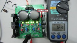
My Placid HD BP is fail , The VDC at rectifier = output but it drop to + - 1 VDC when it connect to Legato . I see a dead insects on QN1 transistor. Now , I measured on Placid HD BP , VDC of TP_VIN = TP_CCS and TP_OUT = TP_SHUNT, no current load on R1 and R2, all heatsink no warm ( cool ) . What wrong with it ? .
Thank you .
Thank you .
Attachments
- Status
- This old topic is closed. If you want to reopen this topic, contact a moderator using the "Report Post" button.
- Home
- More Vendors...
- Twisted Pear
- Placid-BP Bipolar Shunt Regulated Power Supply