BrianDonegan said:Is your mains ground connected to the chassis?
Not yet. I'm just testing the digital part now and that has no connection to the chassis. That is what made it weird. I was thinking some antenna effect...
I will post a pic later...
JeroenR said:
I will post a pic later...
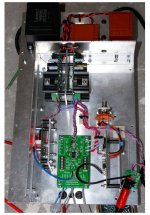
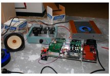
Top view...
Left Tent, middle Metronome and COD, right MUX.
Attachments
")
BrianDonegan said:I think it is static discharge from your hand with no place to go.
The issue is still not solved... When I touch the frame there is a hum/buzz and when I connect the frame to safety ground there is also a loud hum/buzz. Sounds like a 50Hz... I measured the AC voltage between common and frame and it was a whopping 16V!!!
Can it be that because I have mains wire going through holes in the frame that the whole thing becomes in fact a sort of transformer?
Thanks,
Jeroen
Hi,
I have one Q in general,
but refering to sabre ES9008 output...
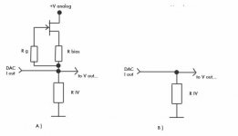
Which one of theese two shoud be better at passive IV?
And, what is the lowest value of R iv that I coul apply,
and not to damage dac chip?
Is the lower value of RIV lowering the distorsion for ES9008, same like in
for instance pcm63 and tda1541 dacs?
Or not?
*
I put, just for the test 1K (at each Iout )
the chip remain the just slight warm...
*
thanks
I have one Q in general,
but refering to sabre ES9008 output...
Which one of theese two shoud be better at passive IV?
And, what is the lowest value of R iv that I coul apply,
and not to damage dac chip?
Is the lower value of RIV lowering the distorsion for ES9008, same like in
for instance pcm63 and tda1541 dacs?
Or not?
*
I put, just for the test 1K (at each Iout )
the chip remain the just slight warm...
*
thanks
Attachments
JeroenR said:
The issue is still not solved... When I touch the frame there is a hum/buzz and when I connect the frame to safety ground there is also a loud hum/buzz. Sounds like a 50Hz... I measured the AC voltage between common and frame and it was a whopping 16V!!!
Can it be that because I have mains wire going through holes in the frame that the whole thing becomes in fact a sort of transformer?
Thanks,
Jeroen
I got some help. The common, safety ground and chassis were not yet connected. After doing this all the hum and buzz was gone, also when touching the frame.
As I did measure a potential difference between frame and common, are there now currents flowing through the frame?
Thanks,
Jeroen
Hello Russ
I want to build a dual mono pcm1794 dac and an asrc with src4192.These will be powered up by Salas v1.0 shunt regulators.One 3.3V regulator for asrc and crystal oscillator, one 3.3V regulator for VDD of both pcm1794 and another two regulators, one each for the analogic side of pcm1794
I saw you have implemented in your schematics a filter (clc) on each VDD/VCC for better supply decoupling.
I want to build the coils myself but did not find anywhere what inductance should they have(found only values about impedance at 100Mhz and DC resistance)
Could you please point me to some values?
Thank you
Hi, I just found out about Twisted Pair and boy have i got some questions!
I am interested in Buying the COD kit. or maybe 2. so the first question is, what is the difference in using one kit stereo, vs. 2x kits each configured for mono??
second. how do you choose the I/V stage resistor? I see that the kit uses 470 ohms while another high end DAC that uses the same PCM1794A chips uses 140 ohms resistors for the IV stage that feed a Jfet input stage.
The same company that makes the DAC also uses 140 ohms in the cd player they also make for their tube buffer stage.
What factors go into choosing the resistor value? I looked at the chips data sheet and couldn't find any info.
I pretty much want to duplicate the whole DAC stage as used in this CD player (using the COD DAC Kit) and add the (out of stock) S/PDIF 4:1 MUX/Receiver and USB Receiver/DAC all into one unit.
Zc
Last edited:
Hi, I just found out about Twisted Pair and boy have i got some questions!
I am interested in Buying the COD kit. or maybe 2. so the first question is, 1)what is the difference in using one kit stereo, vs. 2x kits each configured for mono??
2) second. how do you choose the I/V stage resistor? I see that the kit uses 470 ohms while another high end DAC that uses the same PCM1794A chips uses 140 ohms resistors for the IV stage that feed a Jfet input stage.
3) The same company that makes the DAC also uses 140 ohms in the cd player they also make for their tube buffer stage.
What factors go into choosing the resistor value? I looked at the chips data sheet and couldn't find any info.
I pretty much want to duplicate the whole DAC stage as used in this CD player (using the COD DAC Kit) and add the (out of stock) S/PDIF 4:1 MUX/Receiver and USB Receiver/DAC all into one unit.
Zc
1) Dynamic range is increased when using the chip mono.
2) The most practical consideration is output swing. If you apply gain at the output stage then a lower output swing from the DAC is desirable.
3) That value is perfectly fine. I would strongly suggest however not using an I/V resistor at all and simply using a purpose built I/V stage like IVY-III or Legato 3.1.
Cheers!
Russ
1) is there a limit to this? any reason why a pair of DAC chips couldn't be paralleled per channel? would there be a marked advantage over a single mono chip per channel?
2) Is there a perceivable sonic difference between a high ohm I/V resistor and a Lower Ohm I/V resistor if you kept the final gain the same after the output buffer? One could surmise that it might sound a bit more open and relaxed with less current through the I/V resistor?
2a) How critical is the I/V resistor in terms of sonics? is this the place to spend a few extra bucks and drop a caddock or other "high end" type tweakie resistor in there?
3) I have a specific reason to want to use a I/V resistor stage to start off with. but playing with a legato might be in the works once i get the front end running.
can't offer much on the technical side, but I'm running a PCM1794 via the K&K RAKK DAC using a Lundahl transformer for the IV conversion / outputs. Sounds very good - would like to see your results since the line transformers raised the price of the RAKK considerably.
It's nice to see someone else using this chip with a transformer. That's my intention also.
Well well well, Long time since I revisited this thread. But I have been playing around with COD again since I had some new things to test(JT2 code).
I have a couple of observations which some of you may find useful.
First... I think I have found a very very good setup for COD.
COD --> IVY basic (I will explain later) ---> JT2
Now here is the thing. The output of the COD is pretty darned clean. It does not really need heavy filtering as long as you use the fast rolloff digital filter. So, what I have done is setup IVY with just 392R feedback(I/V) resistors and no filter caps in feedback. None.
Now when I tested this (with my humble gear) the DNR and THD were pretty darn close to Buffalo. And it does sound very very good.
So any of you with a COD and IVY should consider ditching the feedback (filter) caps. I think you will discover a nice change of pace.
To me it sounds like an entirely new DAC.
Cheers!
Russ
When do you expect to have the IVY boards back in stock?
can't offer much on the technical side, but I'm running a PCM1794 via the K&K RAKK DAC using a Lundahl transformer for the IV conversion / outputs. Sounds very good - would like to see your results since the line transformers raised the price of the RAKK considerably.
How would the DC offset of the DAC affect the transformer? Did you use the coupling capacitors?
Russ, do you have an suggestions on how to connect a transformer to the COD? I've been scratching my head about how to deal with the 6mA offset of the DAC chip. There are transformers by Sowter that are designed to handle a DC offset in a DAC, but I'd like to look at other solutions.
Also, does anyone have comments on the Analog Devices application note AN-912?
http://www.analog.com/static/imported-files/application_notes/AN_912.pdf
I can't find where the author mentions what to do about having a DC offset on the DAC. Obviously, we don't want DC in the transformer. If coupling capacitors are used, then the I/V resistors have to go on the COD board because the DAC output pins need a DC path to ground since they are the current source type. I'm concerned that using the coupling caps will create an LC filter in combination with the transformer inductance with unknown results.
No coupling caps are required when using the COD with transformers.
With the center-tap grounded, assuming equal DCR for both primaries, no unbalanced DC is present. Transformers care very much about unbalanced DC, not so much about balanced DC.
With the center-tap floating, assuming well matched I/V resistors, both ends of the transformer will be at the same DC potential and there will be no DC current.
Myself, I use 18ohm resistors on the primary side, 1:5.48 step-up with center-tap floating, and 10kohm pots on the secondary side. Seems to work well. I lack the equipment/skill to do measurements for this type of stuff, but it sounds pleasant enough.
Regards,
John
No coupling caps are required when using the COD with transformers.
With the center-tap grounded, assuming equal DCR for both primaries, no unbalanced DC is present. Transformers care very much about unbalanced DC, not so much about balanced DC.
With the center-tap floating, assuming well matched I/V resistors, both ends of the transformer will be at the same DC potential and there will be no DC current.
Myself, I use 18ohm resistors on the primary side, 1:5.48 step-up with center-tap floating, and 10kohm pots on the secondary side. Seems to work well. I lack the equipment/skill to do measurements for this type of stuff, but it sounds pleasant enough.
Regards,
John
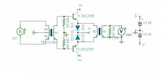
OK, thanks. I forgot that the same DC offset is on each out pin on the DAC.
So, maybe something simple like this would work after all? The diodes are CRD's. The THD would be what ever the transformers have, maybe 0.001% if I'm lucky.
Attachments
- Status
- This old topic is closed. If you want to reopen this topic, contact a moderator using the "Report Post" button.
- Home
- More Vendors...
- Twisted Pear
- COD - Current Output DAC