Hi,
Help appreciated!
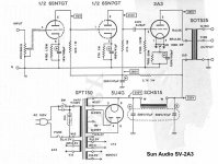
I modified a Sun SV2a3 based schematic for 3 channel operation.
This is a 6sn7-6sn7-2a3 design. Transformer is the Hammond 272jx and 2.5v, 2.5a filament trans for 2a3. My only changes to the power supply is to use a 680 ohm resistor instead of 2.7k ohm to drop the voltage appropriately for the driver tubes + a 250mA rated choke (for additional current draw since this is a 3 channel amplifier).
During first test, the 5u4g (Electroharmonix) flashes brightly and the 3A slo-blow fuse blew. I suspect I am using too high 1st capacitor (47uf) for the 5u4g rectifier. Also I am grounding the 5v filament center tap. I read somewhere in this forum that I may want to disconnect this ground.
The 6sn7 and 2a3 tubes did not seem to power up.....I tested the heater voltage without tubes and they look ok (3v & 6.8v without tubes/load).
Any help on what I should do next is appreciated. This is my first DIY tube amplifer and I am kind of lost on how to proceed.
THANKS!
Marcus
Help appreciated!
I modified a Sun SV2a3 based schematic for 3 channel operation.
This is a 6sn7-6sn7-2a3 design. Transformer is the Hammond 272jx and 2.5v, 2.5a filament trans for 2a3. My only changes to the power supply is to use a 680 ohm resistor instead of 2.7k ohm to drop the voltage appropriately for the driver tubes + a 250mA rated choke (for additional current draw since this is a 3 channel amplifier).
During first test, the 5u4g (Electroharmonix) flashes brightly and the 3A slo-blow fuse blew. I suspect I am using too high 1st capacitor (47uf) for the 5u4g rectifier. Also I am grounding the 5v filament center tap. I read somewhere in this forum that I may want to disconnect this ground.
The 6sn7 and 2a3 tubes did not seem to power up.....I tested the heater voltage without tubes and they look ok (3v & 6.8v without tubes/load).
Any help on what I should do next is appreciated. This is my first DIY tube amplifer and I am kind of lost on how to proceed.
THANKS!
Marcus
Attachments
Tks
Hi, Daniel,
Thanks for the help. I took out the 5v ct connection to ground and tested the amplifier again. Found out that the 5u4g is dead; with a open circuit filaments.
The driver tubes seems ok. But the 2a3s doesn't seem to be lighting up. How do I test/observe the 2a3 to see if they need replacement?
Cheers,
Marcus
Marcus,
Russian and Chinese 5U4Gs are GUANO. Get yourself a US made 5U4GB. TungSol, RCA, and GE made execellent 5U4GBs.
47 muF. is somewhat large. The data sheet shows 40 muF. as typical. 32 muF. in the 1st position of a CLC filter will keep the B+ rail voltage up nicely, without risk of arcing over (very bad). Pile the energy storage up after the choke.
If you have a multi-meter, check for continuity on the 2 big pins of the 2A3; these are the filament connections to the 2A3, pins 1 and 4.
Some 2A3's filaments don't light up that much when energized with voltage so you may have to check to see if they "light up" in a room where the ambient light is low. If the 2.5 volt filament winding from the transformer has a center tap make sure that the CT is going to the return and not one of the 2.5 wires, so to speak.
Daniel
2a3's ok
Hi,
Thanks for the advices. The 2a3 filaments are still connected and yes, they are lighted in a dim room....I couldn't see it well in bright light.
I just purchased a Sovtek 5u4G instead of the original EH 5u4GB and would be dropping the first capicitor to approx 30uF. May still keep the 2nd cap as 47uF. I have a 220kohm bleeder resistor across the 1st cap. I am hoping that this powers supply can power up 3 channels of 2A3s.
If this setup work fine (meaning no more flashes and arcs), I would get a better US made 5UG4. It is a pity to blew up good 5uG4s.
Cheers,
Marcus Tan
The story continues
I received my replacement 5u4G, remove the 5v center tap from ground and the amplifier powers up. I am designing a 3 channel 2a3 SE amplifier for activer crossover to a DIY speaker. At this time, I notice that the high channel is not working but the other 2 are ok. After some checking, I found an incorrect resistor in that channel (mixed in incorrectly by Newark into pack of 5).
However, when this is fixed, the amplifier oscillates. The B+ varies from 250v to 340v. This oscillation is audible mainly through the Bass channel. I searched through the forum, checked and switch the secondary taps of the bass output transformer. The oscillation is gone and now, the high and mid channels are working and their sound is beautiful. But alas, there is no bass (except 40mv of hum") ) from the bass channel......
) from the bass channel......
I am using the lundahl OPT 1623 for top and mid. And the hammond OPT 1627SEA for the bass. What's the right way to connect the hammond OPT?
This is how I am connecting it now:
Hammond 1627SEA
Primary: Red to B+, Blue to Plate, Screen tap (blu/yel) capped
Secondary: Black to +ve of speaker wire. Yellow to -ve of speaker wire. + one wire to signal ground from yellow tap. The other wires are capped off with wire nut.
Thanks!!!!!!
I received my replacement 5u4G, remove the 5v center tap from ground and the amplifier powers up. I am designing a 3 channel 2a3 SE amplifier for activer crossover to a DIY speaker. At this time, I notice that the high channel is not working but the other 2 are ok. After some checking, I found an incorrect resistor in that channel (mixed in incorrectly by Newark into pack of 5).
However, when this is fixed, the amplifier oscillates. The B+ varies from 250v to 340v. This oscillation is audible mainly through the Bass channel. I searched through the forum, checked and switch the secondary taps of the bass output transformer. The oscillation is gone and now, the high and mid channels are working and their sound is beautiful. But alas, there is no bass (except 40mv of hum
) from the bass channel......I am using the lundahl OPT 1623 for top and mid. And the hammond OPT 1627SEA for the bass. What's the right way to connect the hammond OPT?
This is how I am connecting it now:
Hammond 1627SEA
Primary: Red to B+, Blue to Plate, Screen tap (blu/yel) capped
Secondary: Black to +ve of speaker wire. Yellow to -ve of speaker wire. + one wire to signal ground from yellow tap. The other wires are capped off with wire nut.
Thanks!!!!!!
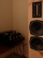
Thanks. A picture of my setup
I finally solved the motorboating issue by using larger filter caps and wiring the output trans ground directly to the star ground (instead of the output tube local ground hub). Hum is around 0.001-2v.
The setup now makes glorious music and its barely broken in! It's active crossover system to Raven R2, PHL 1120 and a side PHL3003.
Thanks Dan and Eli for the help!
Attachments
- Status
- This old topic is closed. If you want to reopen this topic, contact a moderator using the "Report Post" button.
- Home
- Amplifiers
- Tubes / Valves
- Help1 with a 3 channel 2a3 amplifier