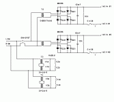
You can't derive two floating supplies from a single supply (well, maybe with additional transformers...) But never mind that, the schematics on their website show completely separate 145V supplies for the output stage.
OTOH, the schematic for the input power supply shows both +400V and +/-190V being obtained from the same transformer. That is impossible with the ground reference at the CT of the transformer. Either the schematic is wrong or...?
If you are talking about something else, then you'll need to provide a schematic or a link.
-- Dave
If you really want to just use one power supply, you need a very big choke. I think it is better and easier to just build 2 power supplies.
http://www.tubecad.com/december2000/page15.html
http://www.tubecad.com/december2000/page15.html
woody said:Dave,
If you look again the raw supply has a tap labled 145v+ and
a tap labled 145v- but in reality this is one 290v supply.
The diagram shows 2 identical supplies of 145v each.
The labels refer to the + and - connections only and do not imply that the supplies are 290v.
Andy
agent.5 said:If you really want to just use one power supply, you need a very big choke. I think it is better and easier to just build 2 power supplies.
http://www.tubecad.com/december2000/page15.html
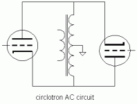
The use of a split primary transformer as a 'balanced choke' is interesting.
However, would not the use of 2 of these ( in effect 4 chokes ) negate the idea of OTL amps i.e. No transformers!
The circlotron has in effect become 2 cathode followers with choke loads.
Andy
poynton said:
The use of a split primary transformer as a 'balanced choke' is interesting.
However, would not the use of 2 of these ( in effect 4 chokes ) negate the idea of OTL amps i.e. No transformers!
The circlotron has in effect become 2 cathode followers with choke loads.
Andy
Circlotron was originally designed by EV WITH output transformers.
Hi Andy,
Theres going to be a transformer in the PSU at some point (even in line op death traps), unless your running off battery power. Running off the mains, I much prefer having chokes and transformers in it.
However, would not the use of 2 of these ( in effect 4 chokes ) negate the idea of OTL amps i.e. No transformers!
Theres going to be a transformer in the PSU at some point (even in line op death traps), unless your running off battery power. Running off the mains, I much prefer having chokes and transformers in it.
I am interested in using a circlotron with a single supply. [In fact, the thing which has so far put me off building one is the complexity of the PSU.]
The use of chokes / transformers looks neat but I have a question that someone may be able to answer.
http://www.tubecad.com/december2000/page15.html
http://www.tubecad.com/december2000/page16.html
On page 16, the article refers to using a split primary / split secondary transformer. [115-0-115 / 115-0-115]
Does the phase of the connections matter ?
Andy
PS Has anyone tried this method?
This method was used by N.H.Crowhurst in its famous "Unity coupled" amplifier.
It's no longer a Circlotron in that sense that anodes and cathodes windings of the OPT become independent and are center tapped.
The beauty of the Circlotron is to use the same single winding for both cathodes and plates loads.
The center tap is just the reference for the drive signal.
You cannot have a better coupling, even using bifilar winding as McIntosh did
But the price to pay is a dual FULL FLOATING PSU.
Yves.
agent.5 said:If you really want to just use one power supply, you need a very big choke. I think it is better and easier to just build 2 power supplies.
http://www.tubecad.com/december2000/page15.html
If you put both chokes on a common core then you have a McIntosh output stage (minus the secondary winding.) What's appealing to me is that you get rid of those big honkin coupling capacitors. If bifilar wound (as in the Macs) then the coupling and bandwidth would almost certainly be better than the tubecad circuit. (Depending, as always, on the quality of the coupled chokes.)
I don't necessarily lust after a 'real' McIntosh amp, but I have to admit that I find the output topology very appealing. Once I came to understand that it is a transformer coupled circlotron I lost interest in the dual floating supply version and have had a transformer coupled version on the to-do list for years. If you leave out the secondary winding and take the output across the cathodes you can even tell your friends it's OTL.
-- Dave
Originally posted by Dave CigOnce I came to understand that it is a transformer coupled circlotron I lost interest in the dual floating supply version and have had a transformer coupled version on the to-do list for years. If you leave out the secondary winding and take the output across the cathodes you can even tell your friends it's OTL.
But if you decide to have a separate power supply for the screens of the pentodes, then you need two power supplies for the output stage anyway.
The use of an additional choke will serve no purpose. Of course, you can use a triode without a screen. But if a better CF uses pentode instead of triode, then you are back to step one.
Well, the amp that I have been saying I'm going to build, but haven't gotten around to would use low rp, high gm triodes running at fairly low voltage. Would probably put together a first-try with 6AS7's running 100 to 125V. The low voltage eases the drive requirements and the low rp , high gm means that I can get away with a low turns ratio in the output transformer (that's right, not OTL.) That would put out only a couple of watts, but more could be gotten from 6C33CB's.
If you want to use pentodes and don't mind running the screens at the same voltage as the plates then you can connect each screen to the opposite plate as McIntosh did. This really is true pentode operation.
BTW: I don't think of the circlotron/McIntosh circuit as PP cathode followers. I think of it as PP concertinas. There may not be a big difference, but I think it's important conceptually if you want to understand how they work.
-- Dave
If you want to use pentodes and don't mind running the screens at the same voltage as the plates then you can connect each screen to the opposite plate as McIntosh did. This really is true pentode operation.
There are different ways to address the screen voltage issue.
BTW: I don't think of the circlotron/McIntosh circuit as PP cathode followers. I think of it as PP concertinas. There may not be a big difference, but I think it's important conceptually if you want to understand how they work.
-- Dave [/B]
I apologize that I am not sure what do you mean by PP concertinas here. My interest in circlotron is that the entire output transformer will be used on each half of the sine wave.
So, a normal PP cathode followers with say two 6550 tubes will need a 5K output transformer; whereas circlotron uses a 1250 ohm output transformer.
I suppose there is more than one way to look at the differences between a plate loaded stage, a cathode follower, and a concertina. The most obvious way is to look where the load is: either in the plate circuit, the cathode circuit, or split with half in each. Another way to look at them is to see where the AC ground reference is for the input signal: at the cathode (plate load), the plate (cathode follower), or half way in between (concertina.)
Both the McIntosh and the circlotron have the signal reference half way between the cathode and plate. To see this you need to remember that the floating power supplies are (ideally) short circuits to AC, so to do AC analysis you can remove them from the picture entirely.
In any case, the choice of load impedance is up to the designer.
-- Dave
Attachments
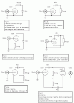
Hey, even if legends are in french, you may follow the process.
Starting with a common cathode, swapping load and PSU.
Then a common plate, redrawn.
Next, a concertina, nothing else that the combination of the two previus.
Last, the Circlotron shown as two concertinas sharing the same load(s)
Yves.
Starting with a common cathode, swapping load and PSU.
Then a common plate, redrawn.
Next, a concertina, nothing else that the combination of the two previus.
Last, the Circlotron shown as two concertinas sharing the same load(s)
Yves.
Attachments
- Status
- This old topic is closed. If you want to reopen this topic, contact a moderator using the "Report Post" button.
- Home
- Amplifiers
- Tubes / Valves
- Circlotron power supply question


