Design of Resonant Input Choke PSU
I have intention to design resonant choke input PSU for A class amp or a pre amp,but I approached some difficulties regarding the way and formulas for calculation of damping resistor and solving the resonances of the supply.
---LC
Let's assume dual mono PSU,tube or SS rectified LC .
---LC
Mains f=50Hz.
Lcrit.=Rload/940 or ~Vout/Imin (Volt-mA-Henry).
For example 20H.
But this is for a non resonant input choke supply.I want my PSU to be of a very low DC impedance with big iron cores and according to this calculation
http://www.qsl.net/i0jx/supply.html
my first choke would be designed for 2.2H and with very,very low DC res.,say 10 Ohm.
Is this valid calculation?
Next I calculate for 100Hz resonance:
f=1/2p sqrt(LC) and determine the resonance cap of 2-3 times the B+ voltage.Say 1uF of high quality dielectric (mica,PP).
Now the problem begins.Because the Rdc of choke is very low the paralel resonance of the trap will not be well damped and we have to use a resistor in series with the resonant cap(or in series with the choke but then my goal fails ????) to stop the circulating AC currents and to damp the trap.
Any ideas how to calculate this resistor?
Morgan Jones sugests 10nF in series with 10k and all that in paralel with the choke but I suppose this is not for the resonant choke input supply.
I also found on diyparadise site resonant choke without R
http://www.diyparadise.com/tunedchoke.html
and with R and in the latter it doesn't match my calculation!!!.
http://diyparadise.com/mar06/gg.html
Is it in real world PSU possibe to achieve 0,5 Q factor with real end reasonable pasive elements?
The Q=R *sqrtC/L for paralel trap and needs increasing the R of the choke for good damping which is in contrary with the Q factor of the next series LC - Q=(1/R)sqrt L/C which needs decreasing the R of the choke for good damping.Also this will be additionally damped with the Rload.
The resonance of the first cap with the first choke(which is series resonant trap and form double pole filter with 40/decade or 12dB/octave roll off) will be easily calculated again but as per Hagerman calculator the result for the damped operation is 400 mili Farads???!!!!!!!
Where is the mistake?
http://www.hagtech.com/theory.html#choke
After that I must try to found the next resonance of the Pi filter between first cap,second choke and second cap and at the end between second choke and second cap separately.
Shall I add the two last caps as in parallel and also add two chokes as in paralell (all together the two branches) and then simply make calculation for the Pi filter,or simply calculate for one branch??
Where shall the resonances of all resonating circuits be? Between 1Hz and 10 Hz for good phase behavior,or they can be around 20 Hz?
And are all those rules applicable also for the SS input resonant choke PSU dealing with chokes of 10 mH and 20kuF?
Quite difficult isn't it?
Your comments and opinions will be highly appreciated!!!
Regards,
Yugovitz
Being that the pre operates in class A, it is quite possible to achieve a non resonant supply of low q with reasonable parts as we arent worried about super low resistance and regulation. A Q less than .7 will be fine and wont ring. Also with a class A amp you wont be ringing said bell so often, its transients that ring it.
Use a high resistance choke, a pair of ~220nF across the choke with their other ends tied together and to ground. For the first section use a large electrolytic cap, follow it by an RC section with a high quality polypropylene capacitor (motor runs are great here, no need to pay the audio tax.) A bleeder resistor can aid in meeting any minimum choke current demands. What voltage and current do you need?
Resonant choke supply part values often have to be trimmed by experiment. Most of the people running resonant supplies are doing it due to transient regulation issues (a choke likes to try and maintain the same current through it) with single side band linear amplifiers. Also at thousands of volts huge effective H values are needed to keep the AC currents down in the inductor. At 50hz, AC peak choke curent= VACRMSin/(1156*L). For a 10H choke at 3,600VAC this would be 312ma.
Unfortunately PSUDII does not do resonant supplies, however, the stepped load function will pick up ringing.
The 10nF-10K pair is used to suppress high voltage transient peaks as the current through the choke (choke input filter) goes to zero during the rectifier off-phase. Also, you probably use full-wave rectification, in which case the frequency is 100 Hz (120 Hz for USA).
But rectified 100Hz go with a lot of harmonics (it is not a pure sine wave), so one cannot get the h.t. line entirely clean with simple resonant filtering, though that helps. Then, a further problem is the exact inductance. There is large varying d.c. through the choke even with a class A load, and the inductance is inversely varying with it. In the end, nett gain in ripple suppression would have to be a matter of testing.
But rectified 100Hz go with a lot of harmonics (it is not a pure sine wave), so one cannot get the h.t. line entirely clean with simple resonant filtering, though that helps. Then, a further problem is the exact inductance. There is large varying d.c. through the choke even with a class A load, and the inductance is inversely varying with it. In the end, nett gain in ripple suppression would have to be a matter of testing.
Yugo said:Design of Resonant Input Choke PSU
I have intention to design resonant choke input PSU for A class amp or a pre amp,but I approached some difficulties regarding the way and formulas for calculation of damping resistor and solving the resonances of the supply.
I would advise to simply fuggeddaboudit. This is a very "faddy" kind of thing. Of course, parallel resonant traps are used quite frequently in RF circuits. However, in those cases, it's needed to trap one frequency, or a narrow band of frequencies. Even though your ripple frequency is 100Hz, it's not a pure sinusoidal 100Hz signal. There are harmonics as well. Trapping out the 100Hz fundamental with a resonant trap will let through all the nasty, off resonant, harmonics moreso than a ripple filter of conventional design.
Exactly. A resonant filter can be tuned to suppress the 100Hz fundamental (I did it once) but it then lets through increased levels of the harmonics compared to a standard LC filter. Nowadays, I'm so much more concerned about getting rid of those higher harmonics that I choose chokes partly for low shunt capacitance.
Thank you very much for your explanation and suggestions.
The idea was to design resonant choke input because it can be made with a smaller core for the first L and than for the second chokes to wound them in several distributed sections thus decreasing the capacitance which can result in a couple thousands pF or maybe much less.
So in this way (I think this idea is not so bad),we can deal with all those nasty high order harmonics.
Although you say that the first choke will pass the nasty frequencies,I don't see reason for such worryies because at the end of the filter the last LC section will suppress the all unwanted harmonics.
Nevertheless,I admit I am not so 100% sure about this.
Have anyone made examination with spectral analyzer regarding this issues?
As per MJ 10nF-10K and 220 nF pair of caps will serve for suppresing turn on -off peaks from the diodes and their reaction with the chokes.This is major problem with SS diodes and L input,less with vacuum rectifiers and second chokes.
The PSU will be for Class A amp consuming around 100mA with B+ of app.300-400 V.The problem which arouse was the calculation of the deQ-ing first choke/resistor in series with the resonant cap.
Which formulae shall I use for this calculation?
1)Rdamp=L/(C*R)
2)Q=R*sqrt(C/L)
3)Rdamp=sqrt(L/C)
Best regards and Happy Easter!
Yugovitz
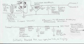
I designed this before I knew what your requirements were. This is the lowest DCR critically damped supply having mV ripple I could come up with without resorting to gigantic computer grade capacitors. The type specified are inverter grade electrolytics, with an oil motor run as the final cap. One could increase the value of the last resistor for phono duty if desired, though ripple is already <2mV. 150R would knock it down about a decade.
Hammond rates its chokes fairly conservatively, it may be possible to run at 100ma without the choke saturating on ac current peaks. Peak AC current in the choke should be around 26ma with 50hz power.
See diagram for preferred input choke snubbing method.
Hammond rates its chokes fairly conservatively, it may be possible to run at 100ma without the choke saturating on ac current peaks. Peak AC current in the choke should be around 26ma with 50hz power.
See diagram for preferred input choke snubbing method.
Attachments
Yugo said:The 10k 10nF method degrades high frequency filtering.
No. The impedance of a 50uF capacitor at 200 Hz is only 16 ohm, decreasing as f rises. In series with the 10K that gives >60 dB reduction, and there are other capacitors further along the line. There is no trace of extra h.t. supply deterioration from these components on a scope/spec.analyzer.
The danger of input choke turn-off transients also exists with tube rectifiers (they turn off as quickly, but usually have higher peak inverse values than s. diodes). Depending on the Q and internal C of the choke, spikes can be several KV with high current amps. The 10 nF then also needs to be several KV, typically ceramic (capacitance drift or tolerance not important). The same precaution would be necessary with the caps over the diodes. The diodes are somewhat protected by the inductance of the power transformer windings, but that may cause ringing itself. It is pretty difficult to quantise this, as even lead inductance may enter into the picture with very short transients. It is also difficult to measure, as a scope probe with a few pF of shunt capacitance could influence the spike (and the probe could blow!).
After all that, I would not worry too much about choke input filter hum etc. reduction. I never had difficulty with ripple coming from that. As said, at the input or pre-amp stages where ripple would be most troublesome, there would have been several further decouplig RC pairs also in the h.t. line.
Regards.
Hi Johan,
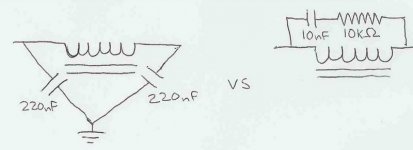
Thats the problem, the pair, at least as discussed in Morgan Jones book, is connected across the choke, giving a short path to HF. Im speaking of choke snubbers and not diode snubbers.
No. The impedance of a 50uF capacitor at 200 Hz is only 16 ohm, decreasing as f rises.
Thats the problem, the pair, at least as discussed in Morgan Jones book, is connected across the choke, giving a short path to HF. Im speaking of choke snubbers and not diode snubbers.
Attachments
Hi Tweeker,
I am not sure that we are "on the same page".
I indicated that the 10K+10nF in the right hand circuit in your drawing will not compromise the h.f. path because of the divider top arm impedance vs the almost short of the output filter capacitor.
What pair, connected across the choke, is giving a short path to h.f.? You cannot mean the pair of 220 nFs; they are not a series short "over" the choke, each of them goes to ground. As ground is the common signal and power point, each 220 will in fact improve matters. The only thing that can give a short path to h.f. will be a capacitor directly connected across the choke, as in the 10K + 10 nF, but then as explained.
If I misunderstand you you will kindly have to be more specific.
Regards.
I havent compared the two snubbers. However, one was made by Morgan Jones in Valve Amplifiers starting at pg 315 (3rd ed). The choke snubbed by the latter method gives a better current waveform and better HF filtering. Scope shots were provided.
The capacitor that the choke is supplying has its own ESL to contend with. At at certain point the capacitors impedance starts rising rather than falling, just as choke impedance starts dropping beyond a certain frequency. The difference may not be significant, especially if the choke is self resonant at a rather low frequency, but why not get as much from it as you can?
The capacitor that the choke is supplying has its own ESL to contend with. At at certain point the capacitors impedance starts rising rather than falling, just as choke impedance starts dropping beyond a certain frequency. The difference may not be significant, especially if the choke is self resonant at a rather low frequency, but why not get as much from it as you can?
That is quite true, but I very much doubt that ESL comes into the picture at power supply harmonics frequencies. Again, what exactly was showed in MJs scope pictures? (Unfortunately I do not have such a book.) As far as amplifier response is concerned, that is why one also bypasses with polyester et al capacitors. This is more necessary in semiconductor amplifiers.
Again, not quite sure how all this is relevant in practical power supply filtering, in the sense that these points are not usually a source of problems.
Again, not quite sure how all this is relevant in practical power supply filtering, in the sense that these points are not usually a source of problems.
No snubber, 10nF 10KR, and 220nF pair to ground were all compared. In the scope shots of the output current, the raw choke had a ^ spike at the 0 diode crossing, it was actually worse in the 10nF 10KR case. It was not present in the 220nF pair case.
I sometimes have things other than rectifier harmonics to filter from my mains, and I cant leave well enough alone (more the later.)
I sometimes have things other than rectifier harmonics to filter from my mains, and I cant leave well enough alone (more the later.)
Johan ,Tweeker
The snubbers we are discussing are proposed by MJ and DO NOT belong to a paralel resonant LC filter I want to design.It seems that this kind of PSU is really tough bite,because I couldn't managed to find adequate literature.
Why resonant?
The idea and the point was that PSU should have minimum DCR up to a couple kHz.
We all know that this is possible (and is the big challenge and goal for the designer) to reach with active regulation either SS or tube.With passive components for that matter we must solve the problem with many resonances(which again lead to another different challenge)and along with that have at the end,the least possible DCR of the supply.
That's why I start and use resonant L input supply of the
----LC
LC
----LC
supply(trying at the same time not to use any R's in any kind of combination-don't know if it is possible),with the first inductor having ONE magnitude less reactance than the usual needed for non resonant L input.Thus at the start, we end with less DCR of the first choke.
What I can not solve is the calculation for the resistor in series with the resonant cap.On some schematics its value is 100 - 200 ohms and another recomendations go from 5k-10k.Of course it depends on some calculation which I don't have.In that trap AC currents seems to be very high!!!
Another problem is,as stated in my first post, further investigation of the resonances(having to solve parallel and series at the same time) and their mutual interactions.Here I also need help!!
If we choose one sub resonance for the target of all parallel and series circiuit's resonances - let say 4Hz ,shall we gain some fruits
if all resonances reach the target of 4 Hz (or the vicinity of 4Hz),or it is better to have many different sub resonance frequencies?
http://www.diyaudio.com/forums/showthread.php?postid=1022171#post1022171
http://www.diyaudio.com/forums/showthread.php?s=&threadid=82686&perpage=10&pagenumber=5
http://www.allaboutcircuits.com/vol_2/chpt_8/6.html
Regards,
Yugovitz
Hi Yugovitz,
I dont see why the 220nF pair would impair a resonant choke, it still has to deal with the 0 diode crossing. Though I could be missing something. You are right about resonant choke design, it is tricky. With resonant choke Id probably go LCRC rather than LCLC as the remainder of the filtering needed will be rectifier harmonics. I often see it stated that parts values need to be trimmed by experiment, theres too many variables for most sims. Circulating currents can indeed be high. Try and look to older sources, they were more common when capacitance cost a orders of magnitude more than present. The Audio Classroom series hosted by audioXpress offers some PSU details along this vein.
DCR is at DC, by definition. I like low DCR, but, once your up a few hz, the capacitors will provide output impedance below DCR.
I dont see why the 220nF pair would impair a resonant choke, it still has to deal with the 0 diode crossing. Though I could be missing something. You are right about resonant choke design, it is tricky. With resonant choke Id probably go LCRC rather than LCLC as the remainder of the filtering needed will be rectifier harmonics. I often see it stated that parts values need to be trimmed by experiment, theres too many variables for most sims.
Circulating currents can indeed be high. Try and look to older sources, they were more common when capacitance cost a orders of magnitude more than present. The Audio Classroom series hosted by audioXpress offers some PSU details along this vein.The idea and the point was that PSU should have minimum DCR up to a couple kHz.
DCR is at DC, by definition. I like low DCR, but, once your up a few hz, the capacitors will provide output impedance below DCR.
Hi Tweeker,
Eli Duttman once on the pages of this forum wrote as per ARRL book,that if L input filter is employed must be followed with another LC pair.
Regarding the PSU impedance,the Walt Jung/Didden Super Regulator's impedance is measured in mOhms!!
The 220 nF pair won't impair L input,neither will increase voltage sufficientlly,but some DIY - ers experienced very badly experimenting with L input and ended with blown fuses or diodes!!!
http://www.diyaudio.com/forums/showthread.php?postid=759106#post759106
Regards,
Yugovitz
P.S. Yeah I've read already Audio Classroom pages long time ago.I think they were Norman Chrowhurst's,weren't they?
Must per ARRL book? Is this an xmitter psu?
If you want critical damping, youl probably have to use an LCLRC, though neither L nor R would have to be all that big in the second section.
The superreg might be in the mOhms, but your DCR is going to be in the ohms regardless, unless your using surplus poco utility iron.
The amp stuff was Norman Crowhurst, the PSU bits in the series were Joseph Marshall.
It was stated that ideally sizing the 220nF capacitor would depend on choke strays reactances. Which could be a sore spot with a resonant choke. He had success with the value in both LT chokes for heater supplies and HT chokes. Most of the posters having trouble were in the uF range. Id recommend this capacitor be AC rated* for more than RMS in if possible.
*a 1600VDC capacitor might be rated for 460VAC RMS.
Yogo,
Just briefly, since you already have a lot of data; in fact I think too much!
At present I have a 100W stereo amp with final stage h.t of 600V and other stages working off 500V regulated. I use a LC power supply filter only, before the regulator. This is for the final anodes only, so not much requirement regarding ripple. No-signal current is 230 mA, full signal = 900 mA. C = 200uF 1KV, etc.
Let me try to measure a few things there. Calculations are OK, but the inductance of chokes vary as the current through them - in a hasty reconnaisance of articles I do not notice much about that. There are leads and such. I will have to construct a special low C high voltage attenuator for the scope and calibrate it for rise time, as I expect KVs without the parallel damper circuit over the L. This to investigate what sort of transients etc. I get with pulsed signal etc.
It will take a few days as I will have to go borrow some KV caps from my ham friends, so don't wait in expectation. Others could lead you through the design procedures. I use graphs for my designs (sign of a lazy engineer), and did not experience unexpected problems with the power supply.
Again to state that the R-C over the choke for L-input filter is supposed to only damp fast inductive pulses at every diode turn-off. As I see it, it should not have a lot to do with inherent power supply ringing. But let me measure. Hope I am not in for a shock - I mean figuratively!
- Status
- This old topic is closed. If you want to reopen this topic, contact a moderator using the "Report Post" button.
- Home
- Amplifiers
- Tubes / Valves
- Design of Resonant Input Choke PSU