I just recently acquired a two tube line-stage and now need to get my act together to build a phono preamp. Very happy listening to my CDs but my vinyl is feeling left out!
I've searched the phono preamp threads but haven't been able to locate a power supply schematic. I've settled on the signal portion with the Thorsten schematic which has a lot of great info in the forums. Still, I can't seem to lock down the power supply.
Any links to a schematic or suggestions greatly appreciated. Thanks.
Attachments
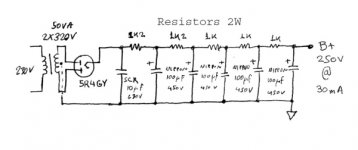
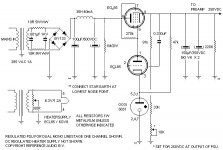
You need a STABLE 250 VDC rail. A stack of 150 V. and 105 V. gas discharge regulator tubes will be just fine. The extra 5 V. is not important.
An unregulated supply >= 320 V. will insure the gas diodes "strike". There are all sorts of ways to get that 320+ V. "Full wave" voltage doubling an inexpensive ($12.12) Triad N-51X is an easy enough way. Use 470 muF./250 WVDC 'lytics in the doubler stack. Follow the doubler stack with a low DCR choke and additional capacitance.
An unregulated supply >= 320 V. will insure the gas diodes "strike". There are all sorts of ways to get that 320+ V. "Full wave" voltage doubling an inexpensive ($12.12) Triad N-51X is an easy enough way. Use 470 muF./250 WVDC 'lytics in the doubler stack. Follow the doubler stack with a low DCR choke and additional capacitance.
The PSU I posted was advised by Thorsten and exibits diminutive ripple. Its no patent of mine. Several people have built the Thorsten phono with that PSU.
A regulated PSU may sound better or not, but what I posted is official and tested. Choice is up to the builder.
P.S.
A friend who has worked in Airforce radar stations told me that gas discharge voltage stabilizing tubes carry a radiation mark on their military packaging and there is clear instruction code of not touching any part if such a tube is broken, cleaning thoroughly the area and removing debris in metal bin due to radioactive elements in those tubes. Is it true? And even further do they need to be installed behind metal when working too? Do they create some weak radioactivity around them when energized? Maybe somebody knows, if its partly correct information or a myth?
Yes its true. The radiation from reference tubes is nothing to worry about though.
There are some other varieties that have significant alpha emitters, mostly spark gap type stuff in serious pulse duties.
Krytrons can contain Nickel 63, but you wont see many in consumer gear.
Radioactive electron tubes.
There are some other varieties that have significant alpha emitters, mostly spark gap type stuff in serious pulse duties.
Krytrons can contain Nickel 63, but you wont see many in consumer gear.
Radioactive electron tubes.
As you said, there is the radiation mark. It doesn't necessarely mean radioactive material. It is warning of ionizing radiation. In the radar the tensions (talking kV) are much higher and gas dissharge can radiate X-ray. In normal audioamplifier which uses 300V I can't think any ways to get X-rays from tube. The tension is just too small.
The question is purely, how much we give energy to the electron and as electron is charged particle it's energy can be said with E=1/2 QU² where E is energy, Q is charge and U is tension. And increasing the tension the energy increases in square. And thinking what kind of photons electron can emit f = h/E where f is frequency of EMradiation, h is Planc's constant and E is energy.
And in military if there is one warning sign it is always treatad same way. Or actually I don't know how in other countries but in Finnish army warnings are taken always seriously. No I am not crazy militarymaniac. We have this national service in Finland. I'm only crazy maniac.
Even normal CRT can radiate with X-rays, microwaves and UV if adjusted incorrectly. Actually CRT emits very much UV but the coating on screen stops it.
And one other thing. What kind of benefits there would be gained by using radioactive material? Most of them are heavy metals and the half-life would eventually change them into led. I'm not very good with gasses but I believe we don't want use heavy element as a dissharging gas.
OR I'm totally wrong and you get bad radiation poisoning. If anyone has first hand information, please share it with us. These were just my thoughts from physics book
Here's one I did. Way overkill probably, but it is dead quiet. Note that the Zener symbols on the output are actually gas regulator tubes (didn't have reg. symbols in the shareware version of microcap).
You could probably get very good performance with the power supply up to the voltage regulator section (delete the current reg. and gas regs.)
The extra bit with transistors is a low impedance voltage source for filament reference. Overkill too. You could do this section with two transistors and still get very good performance.
http://www.diyaudio.com/forums/showthread.php?postid=1170661#post1170661
Sheldon
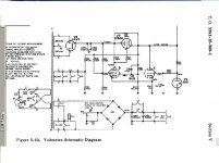
Did I post this? Having a little net trouble here in NJ -- this is the regulator that Jung and Vorhis did in TAA 1982 -- I had some boards made up for a GB a couple years ago (still have a few left) -- the design was for a modification to the Marantz 7 and the Dynaco PAS, thus it was called the LastPAS Regulator:
An externally hosted image should be here but it was not working when we last tested it.
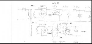
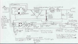
Critically damped choke input all passive phono psu. Effective DCR <1,200ohms. Final sections RC rather than LC for better HF filtering. Heaters are also choke input. Much more expensive than using a 3 legged fuse, but somewhat more EMP resistant. Soft heater and HT starts.
Attachments
- Status
- This old topic is closed. If you want to reopen this topic, contact a moderator using the "Report Post" button.
- Home
- Amplifiers
- Tubes / Valves
- In search of power supply schematic for phono preamp