So my Bevois Valley amplifier has become a staple in my work / computer room and it really sounded great on my Fostex 108EZ backhorns.
Note the past tense.
Anyway, I noticed some warble and squeeeee at certain potentiometer positions and I needed to cure it. I thought it might be the pots, so I swapped 'em out. No luck. Then I removed the pots entirely and decided to go straight from the input to the grid. This got rid of the squeeeee in the right channel, but the left is still a'squeein'.
I then re-soldered all the ground points and checked for ground continuity along both channels and I appear to be looking good there. I also shortened the lead from the input to the grids, thinking I might have been picking up some RF but again, right channel OK, left channel squeeeee.
So I started wiggling stuff.
I noticed that when I touch the frame of the speaker driver, I got a signal from a radio station and some squeeeee. Furhermore, I can vary the degree of squeeeee by touching the amplifier and the speaker frame together, but at no point can I de-squeeeee the system. Also, I tried to ground the negative speaker lead from the left speaker to the right speaker's binding post ground.
Squeeeee.
So, I'm guessing I have an oscillation or a grounding problem, but how the squeeee can I diagnose and fix this. This has been a reall mother squeeeeer all day long and I won't be able to enjoy multiple shots of squeeeee with a squeeeee chaser without fixing this squeeeeeing squeeeeer.
Any ideas?
Kofsqueeeee.
Well, its the Bevois Valley schematic from Morgan Jones' book and I think posting it would land me in the slam or something.
Of course, I have no o'scope, so, in this instance, as in the rest of my life, I'm hosed.
I may actually order one, though, in which case you'll all regret being born as a whole new cavalcade of asenine questions will ensue.
I agree on the oscillation issue. Is there some obvious stuff I could do that woluld potentially cure the problem?
Too many squeeeees tonight. Sorry if I make no squeeeee. Damn NCASQUEEEEE Tournament.
Squeeeeeofi.
Kofi Annan said:Well, its the Bevois Valley schematic from Morgan Jones' book and I think posting it would land me in the slam or something.
How about some hints, then. Single ended or PP? Triodes or pentodes? gNFB? local NFB only? No NFB?
One thing you might try is installing a plate stopper. This consists of a ten turn coil of #18 wire about 7/16th inch in diameter, space wound. Fit a 100R, 2W carbon-composition resistor inside the coil, and wire in parallel. Install as close to the plate pins of the finals as possible. If there is an RF problem, this just might fix it. The inductance of the stopper coil is low enough that it won't have any affect at audio frequencies.
Otherwise, it's difficult diagnosing a problem like this in the blind.
Kofi,
Dumb question: did you ground one of the speaker terminals as in the schematic? The NFB circuit depends on this.
Dumb suggestion: try grounding the speaker frame by connecting it to the grounded speaker wire. If you have a borderline oscillation problem (and you do) then this is not the real fix for that, but it popped into my head and came out of my mouth ...
Miles: I'm surprised you don't have a copy of Morgan's book, if only so that you can follow the discussions around here. It is a good book and worth the money...
Anyway, in a nutshell the amp is PP UL EL84 with ECC88 input/driver. One section of the ECC88 is a common cathode gain stage direct coupled to the second section running as a concertina. NFB is derived from the secondary of the OT and applied at the cathode of the input tube in the usual way. Open loop bandwidth and phase are carefully considered and phase correction is thoughtfully applied in the NFB loop. However, the OT's that Kofi is using are almost certainly not the same as those used by Morgan.... The ECC88 HV supply is regulated with a floating LM317.
-- Dave
Kofi Annan said:
Of course, I have no o'scope, so, in this instance, as in the rest of my life, I'm hosed.
Grid stoppers are the normal advice I think, Fortunately, (sheer luck) I never had an amp oscillate. Has this amp been working sucessfully for a while? maybe a cap or something is on the way out? - just a thought.
Another question - squeeee on both channels?
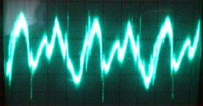
My 2 cents - buy / steal / beg an Oscilloscope. Sooo much fun to be had anyway - got mine, an old Hitachi, for £30 from Ebay - Course i'ts not calibrated anymore but the pictures tell a 1000 words...
If you need convincing - This is my lousy & not regulated PSU in action:
Andy
Attachments
How about some hints, then. Single ended or PP? Triodes or pentodes? gNFB? local NFB only? No NFB?
Uhhh.... wait for it....
Anyway, in a nutshell the amp is PP UL EL84 with ECC88 input/driver. One section of the ECC88 is a common cathode gain stage direct coupled to the second section running as a concertina. NFB is derived from the secondary of the OT and applied at the cathode of the input tube in the usual way. Open loop bandwidth and phase are carefully considered and phase correction is thoughtfully applied in the NFB loop. However, the OT's that Kofi is using are almost certainly not the same as those used by Morgan.... The ECC88 HV supply is regulated with a floating LM317.
What he said. Only I have a simple choke and cap in place of the regulator.
Dumb question: did you ground one of the speaker terminals as in the schematic? The NFB circuit depends on this.
Not a dumb question. I had initially had this problem and fixed it some months ago after rounds of questions just like these. Keep asking the dumb ones-- I require it.
Dumb suggestion: try grounding the speaker frame by connecting it to the grounded speaker wire. If you have a borderline oscillation problem (and you do) then this is not the real fix for that, but it popped into my head and came out of my mouth ...
Will do. I'll take care of that and report back.
Grid stoppers are the normal advice I think, Fortunately, (sheer luck) I never had an amp oscillate. Has this amp been working sucessfully for a while? maybe a cap or something is on the way out? - just a thought.
Another question - squeeee on both channels?
My 2 cents - buy / steal / beg an Oscilloscope. Sooo much fun to be had anyway - got mine, an old Hitachi, for £30 from Ebay - Course i'ts not calibrated anymore but the pictures tell a 1000 words...
I have carbon comp grid stoppers already and the amp has always had a little oscillation / RF problem. I was able to tolerate it for a while by carfully dialing in the right resistance on the volume pots. Also, there seems to be no oscillation / RF on when this is on my main system in the living room. Its only near the cordless phones / wireless router / iMac / radio tower in my computer room that I have the problem.
There used to be squeeeee on both channels, but after I removed the volume pots and randomely resoldered some ground connections it went away in the right channel. Now its just the left channel that's being a pill.
I know its time for an oscilloscope. I need a cheap solution, however, and I have had good recommendations before. I think the advice was to get at least a 50 MHz model but that 100MHz would be better and dual channel. Also, I need to find leads with a high voltage tolerance for tube amp work.
Would this do the trick?
Also, where would you recommend (I'll look on eBay, but another source would help) I pick up leads that would accommodate tube amp work. Do I need only one lead?
I don't know donkey doody about o-scopes, so I need to know what basic accompanying equipment I'd need to order.
OK-- going back out to re-resolder and check the feedback loop. Any advice you can give to your incompetant former UN Secretary General would be much appreciatied.
Kofi
Kofi Annan said:I know its time for an oscilloscope. I need a cheap solution, however, and I have had good recommendations before. I think the advice was to get at least a 50 MHz model but that 100MHz would be better and dual channel. Also, I need to find leads with a high voltage tolerance for tube amp work.
Would this do the trick?
Also, where would you recommend (I'll look on eBay, but another source would help) I pick up leads that would accommodate tube amp work. Do I need only one lead?
I think this scope would do the trick. HP always seemed to be playing "catch up" to Tektronix when it came to scopes, but even as number "two" their scopes were just fine. HP didn't build junk. And the good news is that they usually come cheaper than Tek scopes. While I use Tek scopes mostly today, I do have a pair (one is a parts spare) of HP 1710A scopes, a model roughly similar to this one. The functional unit served me very well for years. With any vintage scope, expect to have to do repairs once in a while. Often similar problems can plague these instruments as old tube amps, mainly bad electrolytic caps.
What you want is called a scope "probe". Eventually you'll want at least two so you can compare two signals (most scopes have two channels, plus a trigger input). The HP 1741A that you're considering has a 20V/division scale (more than most which have 5V/div.), and you'll need a 10:1 probe, which is the most common type. You'll then be able to read +/-800 volts on the screen (more than your probe voltage rating). Watch out for the probe's voltage rating. I've got an assortment of probes, but I bought a pair of "PROBE250" probes from Velleman, and I use them more than the others. They're good for 600 Volts and 250 MHz:
Velleman scope probes
EDIT: PS: The 1741A has a storage display - not necessary, but if you can get it cheap, that would be a nice bonus. Also, a free manual download is available. A manual is very much needed for test equipment. They're too complicated to figure out without schematics, unlike most tube amps.
Thanks! Sounds like a winner.
So, I was wondering...
I am also in the planning phase of a 300b DRD / Monkey amplifier and its got 630V B+. On a 600V probe, I'll obviously be exceeding the rating. Is is possible, however, that I could drop the voltage on the teast probe with a resistor so I can check ripple on the PSU?
Also, this thing apparently has a built-in 1V square wave generator for calibration. Could I also use this for signal testing on the amp? If so, will I need to get another probe or interconnect to plug the signal into the amp?
Dave-- I tried grounding the speaker frame to the grounded terminal and no soap. The bypass cap for the feedback loop is some distance away from the socket lug, so I'm going to try and get that as close as possible and see if that provides any remedy.
Kofi
Unofficially, a 600 volt probe probably won’t have a problem with 630 volts, but you didn’t hear that from me, OK? Please be careful around 600 volts with any probe. Get one of those clip-on tips, which come with the Vellemans by the way, and hook it up with power off. Then power up hands-free. You can make a resistor divider to measure higher voltages, but it will only work at lower frequencies because the probes are capacitance-compensated, and an added resistor divider ruins the high frequency response (looking at power supply ripple will be OK though). If/when you get a scope and a probe, ask again, and we’ll help with divider tricks. You can also get 100:1 probes, but they’re less common. About the internal square wave generator - it’s used mainly for scope probe compensation adjustment and vertical scale calibration. The one in the 1741A is set at 1.4kHz, which is an odd frequency of only slight usefulness for audio testing. You’ll really need a function generator after you get your scope.
It must be said that moving probes around in a powered circuit is far and away the most common way of letting out the smoke. Despite that, many of us do it anyway. So you are officially warned to follow Brian's advice.
That said, you might have a tube that's gone south. It does sometimes happen. Try something silly like replacing the ECC88s and going up a bit in value on the ECC88 stoppers.
Get a scope. It's the single most useful tool in the electronics shop, tied with a good DVM.
That said, you might have a tube that's gone south. It does sometimes happen. Try something silly like replacing the ECC88s and going up a bit in value on the ECC88 stoppers.
Get a scope. It's the single most useful tool in the electronics shop, tied with a good DVM.
Thanks!
UPDATE: I just shortened the leads for the feeldback loop and replaced the loop wire with some sheilded stuff. The oscillation is maybe slightly less noticeable, but no other changes.
I also should confess that I reduced the overall feedback to something other than Morgan Jones' recommendation and this may be causing the issue as well. I'll try and change back to his feedback scheme and see if that makes a difference.
There are 330Rs for gridstoppers on the E88CCs. Maybe 500R would make a difference? Would the increase in gridstopper cause a decrease in input sensitivity?
Also, are there any superdupercheap function generators out there? How about this one?
I know. Too cheap, Kofi.
Yours,
Too-Cheap Kofi
Be daring, go up to 1k.
Well, all I had was 1.5K so I decided to blow your concept of Kofi AWAY and increase even that by another 50%.
Well, of course, its working flawlessly now. All oscillation is completely gone.
I guess I can play with these values to get the right number. Also, I just used some generic metal film and it sounds a little grainy right now. I'll keep listening and see what break-in time does for this, if anything. Carbon comp would be best for this position, I guess, so I'll grab some of those in various values and see what occurs.
Thanks a million for the advice. Again, you all never stop amazing me at how helpful you can be.
Thanks to all.
Now-- about my superdupercheap function generator....
Kofi....
Kofi Annan said:
...
Now-- about my superdupercheap function generator....
Kofi....
If you don't have to have it right away then eBay may be the way to go. I bid on maybe 25 function generators before winning an HP (don't know the model and too lazy to go downstairs and look) for $30 and $10 shipping.
Got a SOAR 2 channel oscilloscope w/2 probes for $60 and about $12 shipping after bidding on maybe 30-40 scopes.
If you need it right away then waiting until the week that nobody else wants what you do probably isn't the way to go.
For a super cheap fuction generator you can use a test CD in a CD player.
For a FREE function generator download this program and run it in an old PC. It is not a good idea to connect your shiny new quad core super computer up to a circuit that contains hundreds of volts unless you are sure that you know what you are doing. I use a USB sound card on an old laptop.
http://www.dr-jordan-design.de/signalgen.htm
Hmmm. To me, a function generator means something that produces square, triangular, and approximately sine waves up to 10MHz with the guarantee that a 10kHz square wave will be near perfect when inspected on a good oscilloscope. Flatness of frequency response within the audio band is also guaranteed by design, making it ideal for measuring frequency response of an audio amplifier.
Any source relying on digits to synthesise a signal (such as a soundcard or a CD player) cannot guarantee a flat response. It doesn't mean they're unusable, but it does mean that they demand a much more knowledgable user to overcome their limitations. A 10MHz function generator will be a little more expensive, but very useful.
Any source relying on digits to synthesise a signal (such as a soundcard or a CD player) cannot guarantee a flat response. It doesn't mean they're unusable, but it does mean that they demand a much more knowledgable user to overcome their limitations. A 10MHz function generator will be a little more expensive, but very useful.
Any source relying on digits to synthesise a signal (such as a soundcard or a CD player) cannot guarantee a flat response.
This is true. Most CD players have 44.1KHz DACs which can't play a 10KHz square wave. It is still a useful tool for troubleshooting sick or dead amplifiers.
The Win MLS software I mentioned has tools that are capable of testing frequency response out to the limits of your sound card. These are not freeware though. You can get a 192KHz sound card for under $150, mine was $99 on sale. Loopthrough response is within .5db to 50 KHz. Synthesized 10 KHz square waves look decent on a scope.
I agree that for serious testing a dedicated generator is the best option. I got a Wavetek at a hamfest for $20, deal.
- Status
- This old topic is closed. If you want to reopen this topic, contact a moderator using the "Report Post" button.
- Home
- Amplifiers
- Tubes / Valves
- Kofi Annan in: "Oscillatin' in the Bevois Valley'"