Perusing old threads, I came across a discussion of 300b drivers. One of the assertions (my paraphrasing which may well be incorrect, so apologies to the discussants) was that high distortion in the driver was actually not all bad because it cancelled some of the distortion in the output valve -- being out of phase with each other.
This raises two questions to me -- the first is that, won't the second valve (the driven valve as it were) produce harmonics of the harmonics making this all a bit for naught, or are those of such low level that they really aren't audible?
And second, assuming that the first is not important, does it make sense to drive a valve with itself so that the spectrum aligns and cancels more totally? This suggests to me that a medium mu valve that can put out a couple of watts might be ideal to drive itself rather than driving a low mu with a high mu. So, does such a tube exist?
Distortion in a good 300B shouldnt be all that high in the first place, so even if they did cancel, you wouldnt want driver distortion to be high.
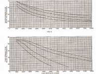
300B distortion vs load and current from WE datasheet.
All curves at 350V anode, with grid bias:
1: 30ma
2: 40ma
3: 60ma
4: 80ma
300B distortion vs load and current from WE datasheet.
All curves at 350V anode, with grid bias:
1: 30ma
2: 40ma
3: 60ma
4: 80ma
Attachments
Authors usually mean second order harmonic cancellation in the articles I've read. If I'm right, under ideal conditions even orders cancel and odds add. My sense is the best that can be achieved in the real world is a driver with sufficient 2nd harmonic content to cause cancellation with the output but with few to no harmonics from 3rd and up. I've played with the technique using a 6CN7 front end driving a beam triode cathode follower into a transmitter tube and was able to get 0.6% at 13 watts SE without feedback. However 3rd harmonic comes up fast at higher powers.
Some relevant reading: http://www.tubecad.com/articles_2001/Inv_Dist_Cancellation/index.html
It would be great to have "A tube" and "Anti-tube" so they compensate each other. ")
Unfortunately, it is impossible. What is possible, to use the shortest linear part of a transfer characteristic. But it is problematic when big power amplificastion is needed: both in microphone and power amplifiers, that's why it is so challenging, so people still continue developing both power and microphone amplifiers, repeating the same mistakes, reinventing wheels...
Unfortunately, it is impossible. What is possible, to use the shortest linear part of a transfer characteristic. But it is problematic when big power amplificastion is needed: both in microphone and power amplifiers, that's why it is so challenging, so people still continue developing both power and microphone amplifiers, repeating the same mistakes, reinventing wheels...
Wavebourn said:Unfortunately, it is impossible..
I can understand 'impractical' or 'ineffective in practice' but why impossible?
rdf said:
I can understand 'impractical' or 'ineffective in practice' but why impossible?
Say, to compensate the 2'nd order you need one device with a member x^2 in a transfer function, and another one with x^-2
No antiworld exist to compensate world.
However, you can always find an equilibrium and trade off something less significant for more significant. This is the art.
Great subject.
As was said, for the most part even harmonics cancel and odd add. Normally 2nd harmonics dominate in a SE stage, so you can somewhat cancel the 2nd and to some degree the higher orders. My experience has been that it's mostly the 2nd that you can cancel significantly.
I guess theoretically the second stage would multiply up the harmonics (i.e., and 2nd order present will generate some 4th order in the subsequent stage), but unless the amount is very large, it drops into the noise fast. 1% of 1% is .01%, below the noise for many/most tube amps.
The problem with cascading like stages is that to get the same distortion characteristics they'd both have to run at the same bias point and same input/output voltages. So it's isn't very useful. Of course you could bridge the load between two like stages, and then you have a push-pull amp.
What I've tried to do with some sucess is just find a driver that has similar harmonic characteristics when operating at it's normal point as the output stage. That increases the cancellation. But you need to be careful that the harmonic content doesn't shift around as the output power goes up; I've done some experiments where 3rd is dominant at low power and then 2nd, then 3rd again as you approach clipping. Doesn't sound good to me.
In my opinion, you don't want to cancel so much of the 2nd that the 3rd becomes dominant in any case until you start to get to clipping.
Pete
Hmmm, I've done it on the bench, once accidentally, and somewhere at home have a Spice sim showing complete 2nd harmonic cancellation with an admitedly rather useless and artifical circuit arrangement built around two 12ax7s (as I recall.) I can post it after work.
My understanding is it works because tubes generate 2nd harmonic in anti-phase with the input. The 2nd harmonic generated in the second tube cancels with the 2nd harmonic 'received' from the 1st, so obviously it's related to the 2nd stage amplification factor as well. I agree with pmillett though that for the most part it's not tremendously useful, or at best done in moderation. To be truly effective the injection of 2nd harmonic distortion of both tubes have to track closely with level across a wide portion of the operating range. The odds of finding the right combination of devices and circuit seem to me pretty low.
My understanding is it works because tubes generate 2nd harmonic in anti-phase with the input. The 2nd harmonic generated in the second tube cancels with the 2nd harmonic 'received' from the 1st, so obviously it's related to the 2nd stage amplification factor as well. I agree with pmillett though that for the most part it's not tremendously useful, or at best done in moderation. To be truly effective the injection of 2nd harmonic distortion of both tubes have to track closely with level across a wide portion of the operating range. The odds of finding the right combination of devices and circuit seem to me pretty low.
True, unless you are using the same tubes for both stages, and the same working points. Of course, this is rather useless in a power amp - there you are condemned to attempts of finding the right combo of driver and driven tube, plus the right combo of working points. In a preamp, you can achieve cancelation relatively easy, by using a common cathode amp followed by a common anode (follower) amp, both the same tubes, DC coupled, with working point chosen to get the same DC voltage across the tubes and the same DC current through the tubes. Of course, the second you put a load to it the cancelation is gone unless you know the load in advance. Even so, the cancellation is dubious - it is really only the 2nd harmonic that can cancel completely.
unless you know the load in advance. Even so, the cancellation is dubious - it is really only the 2nd harmonic that can cancel completely.Sorry for a heresy; it is a solid state example.
Here I combine a voltage follower (upper part) with a voltage to current convertor (lower part). The amp has 2 optimal points:
1. Hi-Fi mode. I0=Imax/2. High efficiency.
2. Hi-End mode. I0=IMax. A voltage follower is happy: it always sees the same emitter current. The minimal possible distortions, especially less on small signals.
The same approach may be implemented with tubes.
The current mirror and voltage mirror circuits provide harmonic cancelation of both even and odd orders. Both can be implimented in tube circuits. Here is an example:
http://www.diyaudio.com/forums/showthread.php?postid=470182#post470182
The trick is that both active devices must track in current. This is not the case for the simpler cascaded driver cancellation scheme, so only even (and mainly just 2nd) harmonics cancel there.
Another example of the voltage mirror is the top active tube load used in the first stage of the Aikido. However, it is not required for a triode stage and is not really effective there.
There is also another approach that is quite effective (even and odd harmonic) for most tubes, as long as they are not operating into screen current distortion or saturation distortion, but it is proprietary.
Don
smoking-amp said:
There is also another approach that is quite effective (even and odd harmonic) for most tubes, as long as they are not operating into screen current distortion or saturation distortion, but it is proprietary.
Don;
are you waiting for somebody to patent your idea?
I prefer to put my ideas in public domain to use them for free.
Wavebourn,
Yet another approach for keeping a constant current thru the tube, with a load attached (attached picture) (needs a 20K resistor or so across the zener - not shown, the Mosfet could be a cathode follower too)
I now view pentodes as triodes with separated output and feedback terminals.
Taking your complementary current source approach further, one can also servo the current source side so as to totally minimize current drawn from the voltage amplifier by the load (will need a P-P voltage amp and P-P current source then). Just put a current sense resistor in the load return lead to the voltage amp pwr supplies, and use the signal to drive the current source so as to zero it. The P-P current source uses separate power supplies so as not draw current thru the sense resistor.
On the "proprietary" linearizer, I am having too much fun right now nulling out distortion from tubes on the analyzer. But I will give you a hint:
I call it 3D bias. It takes the place of the grid bias resistor (for fixed bias case), has two terminals, and 3 adjustments, and uses pre-distortion. Parts count consists of 3 pots, 1 big cap, one low Cinput Mosfet or tube. Think of matching one similar power law curve to another. 3 adjustments are necessary:
1 operating point alignment, 2 operating span match on the curves, and 3 magnitude of correction effect. You have 24 hours to figure out the schematic before this post self destructs!
Don
Attachments
Hmmm...
Compare mine voltage follower loaded by current follower against your voltage follower loaded by a plain resistor... Also, in my case they shift phase on highs equally, in your case FET is in feedback. It is a totally different idea. Triode mode with lowered screen grid DC.
Compare mine voltage follower loaded by current follower against your voltage follower loaded by a plain resistor... Also, in my case they shift phase on highs equally, in your case FET is in feedback. It is a totally different idea. Triode mode with lowered screen grid DC.
rdf said:Found the sim, posted in zip to preserve size and resolution. 2nd cancels and 3rd comes up but interestingly no 4th appears.
It is obvious: take a meandr and change it's porosity. When it equals to 2 all even harmonics starting from 2 disapears; if it is 4 all from 4, if it is 8 - all from 8, and so on...
If your "compensation" is symmetrical it removes even harmonics starting from some number. The question is, what it means sonically? What mechanical systems generate such spector? Transferring sound environment? No. Reflecting environment? No. Broken wood? Yes!
The best example is clarinet... It sounds shrilly, even on pianissimo!
Combining curved transfer functions you don't compensate non-linearities, you change their character. Theoretically it is possible to simulate "anti-tube", but for such purposes we heen a tube and an ideal operational amplifier. Do we have one? If so, why don't we use it instead of the tube we compensate using that already existing ideal ampifier? Because we don't hawe it? If so, how are we going to make the "Anti - Tube"?
Hi, just been reading about this in an old tube design book.
The even harmonics cancel in a push pull output stage because the signal to each tube in push pull is fed in anti phase, even though the transfer function of each tube is non linear therefore causing distortion. The even components are cancelled due to the phasing of even order harmonics w.r.t the fundamental in each tube being the same (like the aikido noise cancelling principal).
Mathematically the even order anode currents from each valve will cancel completely (i guess this is all ideally) but the odd order harmonics are out of phase in the anode currents of the output tubes and the voltages add and double the odd distortion!
Craig
For my SE PT15 amplifier I experimented with different drivers tubes and diver circuits.
I found that most driver tubes reduce the second harmonic but higher even harmonics aren't always reduced and odd harmonics nearly always get worse.
As a reference I've used a low distortion driver. When using this driver the output tube mainly determines the distortion and the second harmonic is at its maximum level (no harmonic cancellation). The benefit of this driver is the odd harmonics are at the lowest possible level, any other driver tube will increase the odd harmonics and decrease the second harmonic.
Harmonic cancellation does work for the second harmonic but I'm not sure about the benefits. In listening tests I've found it difficult to determine if harmonic cancellation or no harmonic cancellation is better.
No harmonic cancellation
Low distortion driver + PT15
measured at 6.4Watt
f1 0dB
f2 -27dB
f3 -42dB
f4 -52dB
f5 < -80dB
f6 < -80dB
Harmonic cancellation
EC91 driver + PT15
frequency=1kHz
measured at 6.4Watt
f1 0dB
f2 -56dB
f3 -40dB
f4 -49dB
f5 -61dB
f6 -73dB
Corne
- Status
- This old topic is closed. If you want to reopen this topic, contact a moderator using the "Report Post" button.
- Home
- Amplifiers
- Tubes / Valves
- Cancelling Harmonics