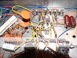
I have an little single ended amp which uses half a 12AX7 to feed a 6BQ5 output tube. The amp runs, but some of the component values have drifted with age. I'm going to gut it and replace the resistors and capacitors with new ones.
Not knowing any better, I intend to simply replace everything with same spec parts. I have a little sketch of the circuit, and I thought I might ask for advice before I start ordering parts. My drawing only shows one channel, but be aware this is a stereo amp. Both channels draw power from the same 6CA4 driven power supply.
I've already taken some liberties with the circuit. The original volume control was a scratchy 1 meg-ohm system, which I replaced with a 10K ohm audio taper pot. (It's what I had on hand.) There was a 860K ohm pot between the signal grids of the two output tubes. Its wiper was connected to ground, and I believe it functioned as a balance control / grid charge leak-off. I removed it, and replaced it with the 470K ohm resistor shown in my diagram. Finally, there were bass and treble controls in between the 12AX7 and the 6BQ5. I removed those completely.
Without further ado, here's my sketch. I'll keenly entertain any suggestions.

There is no need to replace old parts with new ones, unless they are faulty. Some old components are evan said to have good sound properties.
I would rather suggest making changes that have an intended purpose. here are some suggestions to consider:
- the input cap does not seem to have any purpose, other than (possibly) to limit LF extension for the benefit of the OPT (if it is a smallish one).
- you may want to look at the operating point and load-line for the 12AX7. A little more current and higher voltages may be beneficial.
- the common cathode resistor for the 6BQ5 could be replaced with separate ones, with double value.
- the 25uF cathode decoupling cap could be replaced with a larger value, at least 100uF, and maybe a "boutique" brand.
BTW: How does it sound, what would you like to improve ?
SveinB
- the input cap does not seem to have any purpose, other than (possibly) to limit LF extension for the benefit of the OPT (if it is a smallish one).
Rolling infrasonic noise off at the I/P of an amp that employs loop NFB is a good thing. The O/P trafo core is protected against saturation. How small is the O/P "iron"?
Is the 'X7 grid leak resistor really 6.9 MegOhms? 100 KOhms follows the 1:10 rule. Replace the 10 nF. cap with 56 nF., if you use a 100 KOhm grid leak resistor. That puts the 3 dB. down point at approx. 28 Hz.
If a CDP is the source, a 'X7 section provides too much gain. I'd like to see the 'X7 replaced by a 5965 for its high gm, but the power trafo filament winding could get overloaded. The next logical choice is a 12AY7 (mu = 40), which is similar in terms of Rp to the 'X7.
I suspect something in there is faulty. One of the 6BQ5 is developing an orange glow on the plate. It's not the tube's fault. I know the 2100 ohm resistor at the end of the power supply measures closer to 2800 ohms. I also know the 470K plate resistor off the 12AX7 measures closer to 530K.Svein_B said:There is no need to replace old parts with new ones, unless they are faulty.
- the common cathode resistor for the 6BQ5 could be replaced with separate ones, with double value.
- the 25uF cathode decoupling cap could be replaced with a larger value, at least 100uF, and maybe a "boutique" brand.
I've heard others suggest the common cathode resistor for the output tubes might be replaced with separate ones. I agree that is a good idea. It has also been recommended to me that I increase the cathode decoupling cap there while I am at it.
In my limited experience, I'd guess the output transformers are on the small side. They have few markings on them: "U.S. AUDIO / BRONX NY" is all they say. The frame is 2 1/4" wide by 1 7/8" tall.Eli Duttman said:How small is the O/P "iron"?
Is the 'X7 grid leak resistor really 6.9 MegOhms? 100 KOhms follows the 1:10 rule. Replace the 10 nF. cap with 56 nF., if you use a 100 KOhm grid leak resistor. That puts the 3 dB. down point at approx. 28 Hz.
If a CDP is the source, a 'X7 section provides too much gain.
I double checked the grid resistor on the 12AX7. According to the schematic I have, they are supposed to by 6.9M. Mine are colored 6.8M. I measured them around 6.45M/6.35M (left/right). Wouldn't the Fmin work out to around 25 Hz for these values?
Yes, I do recall the gain was a bit much when I first started playing with this amp. I think it became a bit more manageable when I took out the original 1M volume control and replaced it with a 10K audio taper pot. I don't believe this reduces the overall gain, but it lets me turn the knob to a point where the input signal is low enough to work.
I don't know the 1:10 rule. I'll assume it's the ratio of the grid resistor to...? Should I be looking at the relationship between the 12AX7 plate resistor and the 6BQ5 grid resistor? I thought they weren't supposed to be so close in value to each other. Should I be concerned about the coupling cap between the 'X7 and the 6BQ5? It seems small... is the Fmin around 340 Hz? I'd imagine there'd be no bass at all if that were true.
I'd start by replacing the coupling caps to the 6BQ5, one of them is undoubtedly faulty based on your description.
Other mod ideas sound good done a little at a time so you can assess their effectiveness. (i.e. whether you like the resulting changes in the sound) Good way to learn about the design tradeoffs in this particular amplifier design and in tube amplifier design in general.
I would not get too carried away with lowering the LF -3dB point, depending on the available opt primary inductance you may find yourself with a lot more distortion and not much more bass.
Eventually a 12AU7A with some minor component value tweaks would lower the open loop gain by some 14 dB or so and allow you to adjust the values of the feedback resistances for lower gain.. (Note that there might be some stability issues to be resolved with this change, but perhaps not.) I'd get some decent used euro made 12AU7A/ECC82/E82CC for this application.. (eBay)
It takes a remarkably small amount of leakage in a coupling cap to cause problems. You might not see anything amiss, other than huge distortion readings. Or, you might have glowing plates 
I use polyester (Mylar) caps, but a case can be made for various types, depending on what you want to achieve.
I've had the worst luck with old multi-section filter caps. Be sure those 40 uF caps are all good. Old carbon resistors in tube amps can be non-linear with voltage. Depending on their age and condition, I'd replace them with RN-60 or RN-70 metal films, depending on the voltage they see- remember that resistors have both a voltage and power limit. If the construction method relies on ground lugs riveted to the chassis, be sure they aren't corroded and have near zero resistance.
I don't know the 1:10 rule. I'll assume it's the ratio of the grid resistor to...? Should I be looking at the relationship between the 12AX7 plate resistor and the 6BQ5 grid resistor? I thought they weren't supposed to be so close in value to each other. Should I be concerned about the coupling cap between the 'X7 and the 6BQ5? It seems small... is the Fmin around 340 Hz? I'd imagine there'd be no bass at all if that were true.
In the small signal situation, a minimum ratio of 1:10 is in order between the impedances of a driving entity and a driven entity. A 10 KOhm volume control needs at least a 100 KOhm grid leak resistor. Use a 56 nF. cap. between the wiper of the 10 K pot. and a 100K grid leak resistor (metal film for low noise).
The coupling cap. between voltage gain triode and EL84 should be 100 nF. The 10 nF. cap puts the pole at 34 Hz. and that causes a large LF NFB error correction signal, which can saturate the O/P trafo core, to be generated.
 The same thinking applies to the cathode resistor bypass cap. That pole too should be <= 5 Hz. 470 muF. seems (SIC) correct.
Conrad Hoffman said:It takes a remarkably small amount of leakage in a coupling cap to cause problems. You might not see anything amiss, other than huge distortion readings.
If the datasheets are to be trusted, a 12ax7a under those operating conditions generates approx 5% THD at sufficient swing to clip the EL84. The cause of huge distortion readings might be difficult to determine.

If you are going to gut it, i can recommend converting it to an RH84. There is a thread here with extensive info and the original project can be found here.
http://www.tubeaudio.8m.com/RH84/rh84.html
I am running a variation of these now. I'd guess one of he reasons for its excellent performance is the substitution of the global feedback to a much shorter loop that does not include the OPT.
dave
http://www.tubeaudio.8m.com/RH84/rh84.html
I am running a variation of these now. I'd guess one of he reasons for its excellent performance is the substitution of the global feedback to a much shorter loop that does not include the OPT.
dave
Attachments
Well, I replaced the .01 mfd coupling caps on the glowing channel with some Sprague 715P caps of the same value. I know it will be good to increase the capacitance of the coupling between the 'X7 and the EL84, but I just happened to have these parts on hand. The original caps were ceramic discs, if you can believe that. I seems someone had already replaced the caps on one channel, but didn't bother with the other.
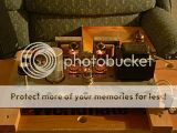
The new caps made no difference in the glowing tube. To be honest, the glow is extremely faint. You need to turn off the lights in the room to see it. It's the one on the left, in case you can't tell.
I think my next step is to separate the cathode bias resistor that is shared between the output tubes. Maybe then I can figure out whether or not the odd tube is pulling more current than the other. Right now I think it is, but I'm guessing one is idling at about 40 ma and the other at 52. I think that is a relatively safe current for these tubes.
I checked the voltages in the circuit while I had it on the table. Most voltages seem a bit higher than the last time I checked it. The drawing I attached in my original post shows the old voltages. Today the outputs are showing 319V/316V at the plate, 298V at the screen, and 8.7V at the cathode. The driver tube is showing 99V/91V at the plate, and 0.25V/0.25V at the cathode. I don't know where the old numbers came from. Maybe I had a bad meter day?
Thanks to everyone who has offered there suggestions so far. Here's my last photo, where you can see her in the light.
An externally hosted image should be here but it was not working when we last tested it.
The new caps made no difference in the glowing tube. To be honest, the glow is extremely faint. You need to turn off the lights in the room to see it. It's the one on the left, in case you can't tell.
An externally hosted image should be here but it was not working when we last tested it.
I think my next step is to separate the cathode bias resistor that is shared between the output tubes. Maybe then I can figure out whether or not the odd tube is pulling more current than the other. Right now I think it is, but I'm guessing one is idling at about 40 ma and the other at 52. I think that is a relatively safe current for these tubes.
I checked the voltages in the circuit while I had it on the table. Most voltages seem a bit higher than the last time I checked it. The drawing I attached in my original post shows the old voltages. Today the outputs are showing 319V/316V at the plate, 298V at the screen, and 8.7V at the cathode. The driver tube is showing 99V/91V at the plate, and 0.25V/0.25V at the cathode. I don't know where the old numbers came from. Maybe I had a bad meter day?
Thanks to everyone who has offered there suggestions so far. Here's my last photo, where you can see her in the light.
An externally hosted image should be here but it was not working when we last tested it.
I see what looks like a 2nd set of I/P jacks. By any chance, is there a power connection for an external tuner?
Yeah, I can believe all sorts of corners were cut in cheap construction.
BTW, before you go to separate EL84 bias networks, try an inexpensive pair of well matched Russian 6p1p-ev/EL84M tubes. The shared bias network will compensate for minor imbalances in the "finals".
The original caps were ceramic discs, if you can believe that.
Yeah, I can believe all sorts of corners were cut in cheap construction.
BTW, before you go to separate EL84 bias networks, try an inexpensive pair of well matched Russian 6p1p-ev/EL84M tubes. The shared bias network will compensate for minor imbalances in the "finals".
Eli Duttman said:try an inexpensive pair of well matched Russian 6p1p-ev/EL84M tubes. The shared bias network will compensate for minor imbalances in the "finals".
You mean 6P14P-EV right?
The DC resistance of the output transformers don't match. One is 300 ohms, and the other 287.
They're both fed from the same 331V supply. On the plate side of the transformer's primary winding, one is 316V and the other is 319V. Unfortunately, I don't recall which was which.
By the math, either the one tube is pulling 50 ma and the other 42, or one is pulling 40 ma and the other 52.
Maybe one of my OPT has a shorted winding or two? Can I just stick 13 ohms resistance in series with it?
I just asked the same thing in another thread, it's due to normal winding differences. That's in fact a far better match than my transformers. In that case I added a few ohms to the lesser side to even them up. In yours though the difference is pretty much meaningless, pretend it's 295 and call it a day.
sorenj07 said:
You mean 6P14P-EV right?
6p14p-ev is correct. I dropped the "4", sorry.
FWIW, I intentionally use lower case letters in Russian types to indicate that phonetic transliteration of Cyrillic to Latin has occurred.
Eli Duttman said:I see what looks like a 2nd set of I/P jacks. By any chance, is there a power connection for an external tuner?
No, this unit never supplied power to an external unit. There was one set of inputs labelled "Tuner" and another set labelled "Phono". There is no phono pre-amp built into this unit. I do not recall there being any difference between the two sets of inputs.
There is a third set of jacks which are connected to the output side of the OPTs. There is some kind of voltage divider circuit or something around them which I've mostly ignored.
I think I'm getting to closer to understanding why my tube is starting to glow. I've calculated between 40ma and 52ma idle current on the EL84. I thought this was OK, based on the tube's data sheets. Well, 48ma is the specified plate current - at 250V. Mine actually have more like 320V at the plate. I found "Duncan's Amp Pages", where he has an Excel based tube load calculator. At 52ma, I'm running my EL84 at about 135%. I'm betting this is why it's starting to glow.
Should I just put a bigger resistor on the cathode?
Is that 320 V from plate to cathode or plate to ground? The first determines plate dissipation. I say go for it. My preference is about 35 ma along with higher B+ voltages on an EL84, though I haven't tried it with feedback. Every brand I measure shows quickly increasing high harmonics in the distortion with currents above that. Plus the higher grid voltage generally results in a higher Class A power out, and that 12ax7 won't do anything other than Class A. The downside is more 2nd harmonic and a very slightly less damping factor.
The 320V is plate to ground. The cathode is about 8.7V (also with respect to ground).
So again, I suppose I can just swap the 80 ohm cathode resistor for something a little bigger? Is there any sense in trying to put some resistance on the plate side instead, or does that just mess up the loading on the tube?
I'm wondering why it's too high in the first place... the resistors around the output tube all seem to be more or less in spec. The only one that seems really off is the 2.1K at the tail end of the power supply. It's a lot closer to 3K.
Could my line voltage throw things that far out of whack? Or maybe they just designed it too hot to begin with?
Ty_Bower said:So again, I suppose I can just swap the 80 ohm cathode resistor for something a little bigger?
That's the way to go. 120-150 isn't a bad place to start. The STC data sheet is very comprehensive.
Is there any sense in trying to put some resistance on the plate side instead...?
Nope.
Could my line voltage throw things that far out of whack? Or maybe they just designed it too hot to begin with?
Could be a number of things. I have plenty of transformers designed for 115 VAC nominal while my local utility is 120 VAC. Filament windings here generally need some series resistance to keep from cooking tubes. Could be your power supply transformer was designed for a heavier current load too. You'll probably find B+ rises further still when you reduce the current through the EL84s. Personally I like EL84s run high voltage low current so for me it's not a bad thing, just keep an eye on plate dissipation.
Edit: Sorry, didn't see both channels share a single cathode resistor. 120-150 is probably too high but not a bad thing, the possibility of damage is reduced starting from that end.
- Status
- This old topic is closed. If you want to reopen this topic, contact a moderator using the "Report Post" button.
- Home
- Amplifiers
- Tubes / Valves
- Tips for rebuilding this amp?