Hello all
I'm building a Je labs St2a3dx and documenting my progress here, I went over my ground scheme on the last page, here. I would apreciate it if could get feedback on the ground layout.
Sorry about the links but I thought it would be a waste to repost all of the pictures here. Thanks for any assistance.
hmm...
So the links work to the other site but the pictures don't work for you? Wierd, it works for me, but that doesn't mean anything.... Oh I bet you have to register... I'll try and link them.
One
Two
Three
http://audiokarma.org/forums/attachment.php?attachmentid=43825&d=1174285842
Maybe those worked.
So the links work to the other site but the pictures don't work for you? Wierd, it works for me, but that doesn't mean anything.... Oh I bet you have to register... I'll try and link them.
One
An externally hosted image should be here but it was not working when we last tested it.
Two
An externally hosted image should be here but it was not working when we last tested it.
Three
http://audiokarma.org/forums/attachment.php?attachmentid=43825&d=1174285842
Maybe those worked.
Three!
I should have done this first! Sorry
Text...
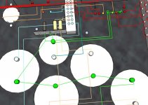
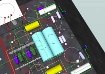
First picture - center tap to the first 20uf cap, the cap is connected to the ground at the adjacent center ground lug, the 12 gauge copper wire bus starts there at the cap as well. The next connection is the center tap of the 6.3v, then the 200k resistor, the bus then makes a stop at each cap in order, 100uf, 50uf, 50uf.
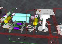
Second Picture - Bus wire travels across the chassis and ends above the two 20uf/500v filter caps (big ones in the center)
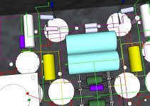
Picture three - Each channel procceeds the same. Input jack to 100k resistor to 1k resistor to 22k cathode and 100uf bypass cap to the ground bus wire after the filter caps.
Input jack is isolated, ignore were it appears that each channels run through a ground lug in picture 3, only 2 ground points exist, one next to the 20uf cap at the power supply end and one next to the main power plug safety ground.
Please let me know if you see something which is gount to cause me problems. Thanks!
I should have done this first! Sorry
Text...
First picture - center tap to the first 20uf cap, the cap is connected to the ground at the adjacent center ground lug, the 12 gauge copper wire bus starts there at the cap as well. The next connection is the center tap of the 6.3v, then the 200k resistor, the bus then makes a stop at each cap in order, 100uf, 50uf, 50uf.
Second Picture - Bus wire travels across the chassis and ends above the two 20uf/500v filter caps (big ones in the center)
Picture three - Each channel procceeds the same. Input jack to 100k resistor to 1k resistor to 22k cathode and 100uf bypass cap to the ground bus wire after the filter caps.
Input jack is isolated, ignore were it appears that each channels run through a ground lug in picture 3, only 2 ground points exist, one next to the 20uf cap at the power supply end and one next to the main power plug safety ground.
Please let me know if you see something which is gount to cause me problems. Thanks!
Attachments
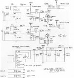
Drawing-challenged me still couldn't make heads or tails of it. But anyway, I marked up the schematic to show how I would do the grounding and added a cap which might save you some grief. Also, I would strongly consider putting either a reverse-biased diode or a neon lamp between the grid and the cathode of the driver tube. The segment between the output stage star and the power supply star should be short and thick.
edit: I forgot to move the chassis ground. Corrected.
edit: I forgot to move the chassis ground. Corrected.
Attachments
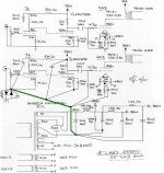
Think of currents running downstream. We start at the top with the supply (being careful not to break into a high ripple current loop). We then cascade down, with successive stages dumping less and less current in until we reach the earth/safety ground. It makes logical sense since the stages that draw the most current are closest to the power supply ground node, i.e., we've minimized IR drops along the bus.
Diodes: I use 1N4007 because I have about 10,000 of them.
Resistor: Not terribly critical. 15R, 33R, something like that.
Cap: Not critical, either, but use one with good RF properties. 0u01 ceramic disc is what I use because, again, I've got about 10,000 of them.
This is how I did the grounding in my power amps and preamp, and not a hint of hum or buzz despite three-wire line cords and no ground isolating switches.
Also, Nelson Pass has written something about this recently, but apparently he uses a bridge rectifier instead of the two diodes. Poke around www.passdiy.com a bit and I'll bet you'll find his suggestions. If they contradict mine, believe him, not me.
ok, I did it
So I went to digi-key and picked up the following.
(4) 1N4007FSCT-ND DIODE GPP 1A 1000V - $0.44
(10) 1460PH-ND CAP .01UF 500V CERAMIC DISC - $1.66
(5) PPC15BCT-ND RES 15 OHM .50W 5% MF FUSIBLE - $2.57
Pretty cheap. Your way seems easier then running a bus everywhere. So I gather all of the power grounds at the first cap, then with a thick wire run a line to the other stages and then to the diodes, resister, and disc cap which is connected to the chassis near the inputs?
Thanks again for your assistance.
- Status
- This old topic is closed. If you want to reopen this topic, contact a moderator using the "Report Post" button.
- Home
- Amplifiers
- Tubes / Valves
- Ground scheme