How about this for a super simple P-P amp? Would it work? Would it even sound good?
Apparently this topology has good frequency response at the extremes due to the low output impedance of the followers, and the fact that there is no DC through the transformer primary (with a properly adjusted bias)
The circuit as it is is quite low gain and you would need a preamp with a large voltage swing...
The mains toroid is there to step the signal up to drive the followers. Apparently these do quite a good job of this, with a wide bandwidth and low distortion. The aim here is simplicity.
Both power supplies are floating.
It would be cool to build something like this for an experiment. I don't know why more amps aren't designed like this! Any thoughts?
(Simplified schematic, some vital parts missing)
Last edited:
bigwill said:How about this for a super simple P-P amp? Would it work? Would it even sound good?
Apparently this topology has good frequency response at the extremes due to the low output impedance of the followers, and the fact that there is no DC through the transformer primary (with a properly adjusted bias)
The circuit as it is is quite low gain and you would need a preamp with a large voltage swing...
The mains toroid is there to step the signal up to drive the followers. Apparently these do quite a good job of this, with a wide bandwidth and low distortion. The aim here is simplicity.
Both power supplies are floating.
It would be cool to build something like this for an experiment. I don't know why more amps aren't designed like this! Any thoughts?
"Both power supplies are floating. "
That's why ! And four in a stereo unit.
I've something similar boiling using 6CW5 penthodes and an 1K2 load.
Bandwith is dead flat well over 200Khz and THD below 0.3% at 13 Watts.
The driver uses the "classic bootstraped differential pair" scheme with two triodes and no IST.
First stage is an LTP PI.
I've checked hi gain penthodes (6EJ7) in bootsraped LTP PI, no need for another stage.
However, the large Rp make the boostrap very very efficient, the result being a miniscule damping factor (around 1,5).
A form of transconductance amplifier

More to do !
Yves.
Re: Re: Simple circlotron amp
What if you used a pair of 6C33C-Bs?
Edit: n/m I think I misunderstood
If I were to build this I wouldn't use NFB, not because I'm dead against it but it would make the whole thing a lot simpler, and the Susan Parker mosfet amp doesn't use NFB and those are supposed to sound good
Yvesm said:
However, the large Rp make the boostrap very very efficient, the result being a miniscule damping factor (around 1,5).
What if you used a pair of 6C33C-Bs?
Edit: n/m I think I misunderstood
If I were to build this I wouldn't use NFB, not because I'm dead against it but it would make the whole thing a lot simpler, and the Susan Parker mosfet amp doesn't use NFB and those are supposed to sound good
Hi!
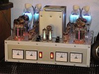
I've build a Circlotron with 6C33CB - definitely NOT a beginner's project, but very worth the effort. See thread: Uli's Circlotron
Uli
I've build a Circlotron with 6C33CB - definitely NOT a beginner's project, but very worth the effort. See thread: Uli's Circlotron
Uli
Attachments
- Status
- This old topic is closed. If you want to reopen this topic, contact a moderator using the "Report Post" button.