X10D Mods
Hello Tube_Dude !
Not shure to have understood :
For a gain of 6, the resistor change from 1.5k to 22k : OK
So the ratio for resistors is 15 (not 5)
Now for the // cap : change the original 220pF (on attached scheme) for a smaller one with a ratio of 15 ? No ?
220 pf / 15 = 15pF
So sorry for my ignorance !
R.C.
Attachments
Re: X10D Mods
Hi Ciu
Sorry for the delay I have been to busy...
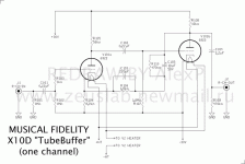
The gain is given by the formula I give in my previous post.
Imagine (all the people..... ) that you change the 1k5 resistor for a 1 Ohm resistor , we have:
1+ (1/ 4k7 ) that give
1+ (0,0002 ) or a gain of ~ 1
Now if you change the 1k5 for a 4k7
we have
1+(4k7/4k7 ) that give a gain of 1 +(1)= 2
Remark, that we have passed from a feedback rsistor value of 1 to 4.700 (4.700 times greater ) and the gain of the stage only have become the double .
Then for a gain of 6 the value of 22 k is absolutely correct.
I hope to be clear now...
Regards
PS: In your last schematic the 4k7 resistor become 8k2 , so for a gain of 6 the 1k5 resistor must become ~41k or a more normal value of 39 K
Ciu said:Hello Tube_Dude !
Not shure to have understood :
For a gain of 6, the resistor change from 1.5k to 22k : OK
So the ratio for resistors is 15 (not 5)
Hi Ciu
Sorry for the delay I have been to busy...
The gain is given by the formula I give in my previous post.
Imagine (all the people.....
) that you change the 1k5 resistor for a 1 Ohm resistor , we have:1+ (1/ 4k7 ) that give
1+ (0,0002 ) or a gain of ~ 1
Now if you change the 1k5 for a 4k7
we have
1+(4k7/4k7 ) that give a gain of 1 +(1)= 2
Remark, that we have passed from a feedback rsistor value of 1 to 4.700 (4.700 times greater ) and the gain of the stage only have become the double .
Then for a gain of 6 the value of 22 k is absolutely correct.
I hope to be clear now...
Regards
PS: In your last schematic the 4k7 resistor become 8k2 , so for a gain of 6 the 1k5 resistor must become ~41k or a more normal value of 39 K
X10D Mods
Hello Tube_Dude
For a gain of 6 you must change the 1.5 K resistor for 22 k. As the resistor is 5 times greater , the // capacitor must be ~ 5 times smaller for the same time constant
That was the beginning of my trouble ! 22k /1.5k = 5 ?
In my study case, for a gain of 6, the resistor changes from 1.5k to 39 k, OK !
And the value of the cap, how to calculate, where do you find the ratio ? Any recommanded technology for the cap ? Voltage (>= 30v ?)
Many thanks for your patience !
R.C.
dzkh63 said:Dear Tube_Dude
The Musical Fidelity X-10D I can't find a 4.7k resistor.I want to learn how to adjust the gain,can you tell more detale.Thank You
Is your schematic , the one in post # 21 ?
dzkh63 said:Dear Tube_Dude
Yes,it's post#21
Hi ,
The overall gain is given by:
1 + ( R106 / R 104 )
in the case of post #21 we have
1 + ( 1,5K / 8,2k ) = 1. 18
For a overall gain of 2 you can use R106 , 8,2 K
For a gain of 3 use R106 , 16,4 K .........................
Greetings
XD10
Hi RC,
I have a clone XD10. I am interested to know the ouutcome of your mods if you dont mine sharing. I have change all the supply cap with panasonic FC 2200uF/35V, change the diode with ultra fast soft recovery and bypass the diode with 0.1uF caps. All the transistors in the power supply removed/bypass. I also upgraded all the caps in the circuit. Did u manage to inxrease the gain?
Thanks
NikS
Re: XD10
I know this thread is a little old, but.......!?
I'm running mundorf supreme 4.7uf on the output, but there are a couple of 0.22uf cap in the audio path. What would be a good upgrade here? I don't want to change the gain just improve the quality of the components.
I have already ordered Panasonic FC's for the supply section and I'm also waiting for hexfreds to replace the diodes.
What other upgrades should I consider?
Thanks Ian
niksh said:Hi RC,
I have a clone XD10. I am interested to know the ouutcome of your mods if you dont mine sharing. I have change all the supply cap with panasonic FC 2200uF/35V, change the diode with ultra fast soft recovery and bypass the diode with 0.1uF caps. All the transistors in the power supply removed/bypass. I also upgraded all the caps in the circuit. Did u manage to inxrease the gain?
Thanks
NikS
I know this thread is a little old, but.......!?
I'm running mundorf supreme 4.7uf on the output, but there are a couple of 0.22uf cap in the audio path. What would be a good upgrade here? I don't want to change the gain just improve the quality of the components.
I have already ordered Panasonic FC's for the supply section and I'm also waiting for hexfreds to replace the diodes.
What other upgrades should I consider?
Thanks Ian
This is the diagram of the clone sold on ebay!
If you are building, use decent diodes and Panasonic FC 1000uF caps on the supplys and also choose something nice like Mundorf coupling caps on the output. These are the parts fitted if you upgrade the X10D. Also its worth getting cryo treated valves as they tend to be less microphonic.
If you are building, use decent diodes and Panasonic FC 1000uF caps on the supplys and also choose something nice like Mundorf coupling caps on the output. These are the parts fitted if you upgrade the X10D. Also its worth getting cryo treated valves as they tend to be less microphonic.
Attachments
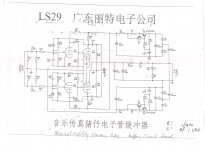
Does anybody have the part list of Musical Fidelity X10D?I have a pcb from x10d and i want to built one by myself.
No Thanks needed honest! have you even come back to look?
No Thanks needed honest! have you even come back to look?
I am sorry for the delay.I didn't visit this forum often.I look your answer but i don't want this,i want the part list of x10d.Or if you know the voltage of the C101,C102,C103,C104 and the recistance of the R104.Thank you very much for your attention.
I'm fairly sure all the info is in the schematic I posted.
Why are you after a list of parts??
Ultimately you have right.The schematic is the same as the original x10d.I want the part list because i have a only a pcb of X10D and i want to know all the necessary parts that i need to built it by myself.Thank you very much for your help.
- Home
- Amplifiers
- Tubes / Valves
- Musical Fidelity X10D schematic