Pending!!
arvin,
I'm at work at the moment - Friday OZ time.
I have a full circuit trace schematic in a work book at home from when I did an upgrade on one. Will check this thread again on Monday - if no ones obliged by then I will scan and post then.
Also have done the same for XL-Pre and the Phono. Do you want them posted too?
Cheers,
Ian
Re: About X10D Mods
I'm new to tube circuits but I don't think that you can get more gain since it is a cathode follower circuit.
I'm looking forward to seeing the X10 schematic and comparing with my
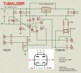
Audiodigit Tubalizer. That too is a simple buffer with a gain of 0.98 but works (supposedly) from 12V although I can only make it sound good with 24V.
I'd love to build both circuits and see which one is better.
Here's my schematic for comparison:
Hi,Ciu said:Hello Gingertube !
I'm also interested , if you have any document about the X10-D, and if you have any advice about sound quality improving, and how to give more gain (actually 0.98 ?)
Many Thanks !
R.C.
I'm new to tube circuits but I don't think that you can get more gain since it is a cathode follower circuit.
I'm looking forward to seeing the X10 schematic and comparing with my
Audiodigit Tubalizer. That too is a simple buffer with a gain of 0.98 but works (supposedly) from 12V although I can only make it sound good with 24V.
I'd love to build both circuits and see which one is better.
Here's my schematic for comparison:
Attachments
Re: Re: About X10D Mods
Arvin, To be sure - X10-d version 1 right? not the V3? - all the rest applies to the V1 so sorry if its inapplicable.
I don't think it is? If this is the V1 were talking about Its just run under 100% feedback, SOMEWHERE, perhaps on this very site theres some other information (I'm not sure) regarding changing the feedback resistor to give you a gain of 2 (or more) Think pre-amp
Gingertube, I too would love to see the schematic for the X-Pre, I sold mine on before I really started tweaking... seem to remember an op-amp in there somewhere?
As for X10d modifications, Hmmmm well theres a list! Take a look at rockgrotto http://www.rock-grotto.co.uk/ might get some hints by surfing around there, theres also a pre arranged upgrade kit.
A lot of talk for the small X-series centres around the PSU which is basically just a 12v transformer. This is one case where a new 12VAC trafo + some better wire will really help (AND give you an OFF button).
Personally, which is all tube rolling is, I found the 6922's installed nasty-horrid. Changed to E88CC's and there was a marked 'change' which I prefered. then theres that 6N23-P thing which I havent tried...
hope thats useful.
Andy
Arvin, To be sure - X10-d version 1 right? not the V3? - all the rest applies to the V1 so sorry if its inapplicable.
Sonusthree said:I'm new to tube circuits but I don't think that you can get more gain since it is a cathode follower circuit.
I don't think it is? If this is the V1 were talking about Its just run under 100% feedback, SOMEWHERE, perhaps on this very site theres some other information (I'm not sure) regarding changing the feedback resistor to give you a gain of 2 (or more) Think pre-amp
Gingertube, I too would love to see the schematic for the X-Pre, I sold mine on before I really started tweaking... seem to remember an op-amp in there somewhere?
As for X10d modifications, Hmmmm well theres a list! Take a look at rockgrotto http://www.rock-grotto.co.uk/ might get some hints by surfing around there, theres also a pre arranged upgrade kit.
A lot of talk for the small X-series centres around the PSU which is basically just a 12v transformer. This is one case where a new 12VAC trafo + some better wire will really help (AND give you an OFF button).
Personally, which is all tube rolling is, I found the 6922's installed nasty-horrid. Changed to E88CC's and there was a marked 'change' which I prefered. then theres that 6N23-P thing which I havent tried...
hope thats useful.
Andy
Re: Re: Re: About X10D Mods
Actually I'll take that back or modify it SHOULD really help. generally the power supply in the X10 is a 60v hack making beautiful use of the fact that its all class A. - IMHO a clever circuit
I STILL need to do this PSU upgrade to my set. (x-10d, x-cans & x-dac) - transformers bought in 2004!
Now thinking aloud:
Suppose you dumped all that power supply circuit and just made a nice linear 60v PSU? without a voltage doubler in site? couldn't you then get rid of the input cap completely? grid of V1 would now be at ground?
And there is space for another board in there too....
Also, One other thing. Check the heater voltages of the 2 tubes, you may find that interesting.
Andy
andrew_whitham said:A lot of talk for the small X-series centres around the PSU which is basically just a 12v transformer. This is one case where a new 12VAC trafo + some better wire will really help
Actually I'll take that back or modify it SHOULD really help. generally the power supply in the X10 is a 60v hack making beautiful use of the fact that its all class A. - IMHO a clever circuit
I STILL need to do this PSU upgrade to my set. (x-10d, x-cans & x-dac) - transformers bought in 2004!
Now thinking aloud:
Suppose you dumped all that power supply circuit and just made a nice linear 60v PSU? without a voltage doubler in site? couldn't you then get rid of the input cap completely? grid of V1 would now be at ground?
And there is space for another board in there too....
Also, One other thing. Check the heater voltages of the 2 tubes, you may find that interesting.
Andy
Be careful when tube rolling with the X series. I had the X10D and tried some Mullard ECC88's. Sounded very treacly, I liked the stock much better.
The power supply would seem to be the best upgrade. Cap changes might also help. Remember this is a tuned circuit so indescriminate swapping of components may not give you the result you are expecting.
Shoog
The power supply would seem to be the best upgrade. Cap changes might also help. Remember this is a tuned circuit so indescriminate swapping of components may not give you the result you are expecting.
Shoog
Re: About X10D Mods
Well Ok now, I am NOOOoooo expert in feedback (or much else really) but, so I can be corrected by someone is, the 10uF cap is passing most of the audio band so I'd direct my attention to the 1.5k resistor and reduce it BUT it is part of a step network, so....
Actually I'd pull out the 10µ cap, altogether first, and try not frequency dependant feedback. The problem is that When Messing around with someone elses circuit its not immediately obvious what the design intent was. (or maybe it is, I dont know)
Beware though, the board on my X10D is er, 'not healthy' I get the idea that they arent the most de-solder friendly bits of kit.
In my defence, I got it like that. (although you can buy a copy of the board on ebay for a few dollars)
Shoog: tube rolling in the x-series, its healthy exercise.
The Mullard E88CC was the one I preferred! I guess it must just suit my system - or my ears. I found the stock really thin in comparison. Same for the X-cans. Not that the tube is supposed to make any difference under this much FB... but anyway.
Andy
Ciu said:To andrew_whitham
Wich resistor I have to change to modify the gain ; I see a 470k // Cap 10µ, and at the other side, near V1 Cathode, another resistor 1.5K // 220pF ?
To go Up, or to go down in values ?
Thanks !
R.C.
Well Ok now, I am NOOOoooo expert in feedback (or much else really) but, so I can be corrected by someone is, the 10uF cap is passing most of the audio band so I'd direct my attention to the 1.5k resistor and reduce it BUT it is part of a step network, so....
Actually I'd pull out the 10µ cap, altogether first, and try not frequency dependant feedback. The problem is that When Messing around with someone elses circuit its not immediately obvious what the design intent was. (or maybe it is, I dont know)
Beware though, the board on my X10D is er, 'not healthy' I get the idea that they arent the most de-solder friendly bits of kit.
In my defence, I got it like that. (although you can buy a copy of the board on ebay for a few dollars)
Shoog: tube rolling in the x-series, its healthy exercise.
The Mullard E88CC was the one I preferred! I guess it must just suit my system - or my ears. I found the stock really thin in comparison.
Same for the X-cans. Not that the tube is supposed to make any difference under this much FB... but anyway.Andy
Re: Re: About X10D Mods
Hi Andy
Are you sure that is not a 15K resistor?
For a overall gain of ~4 ...
andrew_whitham said:so I'd direct my attention to the 1.5k resistor and reduce it BUT it is part of a step network, so....
Andy
Hi Andy
Are you sure that is not a 15K resistor?
For a overall gain of ~4 ...
Re: About X10D
If the gain is given for 0,98 ( ~1) , then the resistor must be 1.5 K Ohms...
Salut...
Ciu said:
One (one is noted 15k ), another (from Alex ZeusLab ?) is noted 1.5k
Where is the truth, I don't have the board near me...
The gain is given for 0.98 ... No ?
R.C.
If the gain is given for 0,98 ( ~1) , then the resistor must be 1.5 K Ohms...
Salut...
X10D Mods
Hello Tube_Dude !
How do you calculate the gain ?
Is only the 1.5k resistor to change ? The cap // also ?
I bought this to give some more level to the Monica DAC I built , but nothing to do with a buffer with unit gain, unless you would gave me a miraculous recipe to give a gain of 6 or more?
I understood the PSU should be changed, for a symetric -+30v, that is quite simple for me, but in the schematic, no idea !
Thanks for any advice
R.C.
PS : 900 kawa vintage 1975, your's ?
Re: X10D Mods
Bon soir , Ciu
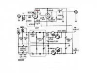
The gain is given by 1 + ( 1.5k/ 4.7K ), so in your case , you have a gain of ~ 1.3 .
For a gain of 6 you must change the 1.5 K resistor for 22 k.
Don't change the 4,7 K resistor , because it provide the DC bias condition of the input tube.
As the resistor is 5 times greater , the // capacitor must be ~ 5 times smaller for the same time constant...
Hope it help.
No , it's a 2003 Suzuki GSX 1400...")
http://www.lerepairedesmotards.com/actu/2001/actu_010520roadstergsx1400.htm
Çá rule!!
Ciu said:Hello Tube_Dude !
How do you calculate the gain ?
Bon soir , Ciu
The gain is given by 1 + ( 1.5k/ 4.7K ), so in your case , you have a gain of ~ 1.3 .
For a gain of 6 you must change the 1.5 K resistor for 22 k.
Don't change the 4,7 K resistor , because it provide the DC bias condition of the input tube.
As the resistor is 5 times greater , the // capacitor must be ~ 5 times smaller for the same time constant...
Hope it help.
PS : 900 kawa vintage 1975, your's ?
No , it's a 2003 Suzuki GSX 1400...
http://www.lerepairedesmotards.com/actu/2001/actu_010520roadstergsx1400.htm
Çá rule!!
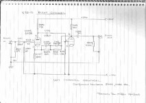
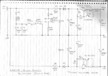
And here is the Power Supply schematic
I replaced all 35V rated electrolytics with 50V rated Sanyo and all 1N4007 diodes were replaced withn BYT11-800 Ultrafast Soft Recovery diodes.
CAUTION: Floating around the web are upgrade instructions for the X10D which include replacing TR1, TR2, TR3, TR4 with BC640. Note that two of the original transistors are BC327 (PNP) and 2 are BC337 (NPN). That "upgrade" would produce smoke.
Cheers,
Ian
Attachments
- Home
- Amplifiers
- Tubes / Valves
- Musical Fidelity X10D schematic