Hello,
Would the following circuit work and give 12VDC? Excuse the schematic if some of the symbols are incorrect - I have limited software for doing this. The caps are non-polar electrolytic. The MC78T12CT is a Fairchild positive voltage regulator - 12V 3A.
Thank-you,
Charlie
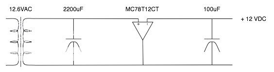
Would the following circuit work and give 12VDC? Excuse the schematic if some of the symbols are incorrect - I have limited software for doing this. The caps are non-polar electrolytic. The MC78T12CT is a Fairchild positive voltage regulator - 12V 3A.
Thank-you,
Charlie
cbutterworth said:I meant to add a bridge rectifier made from 1N4001 diodes./B]
Make sure they can carry enough current.
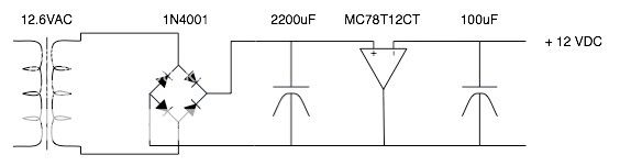
cbutterworth said:Sorry,
I meant to add a bridge rectifier made from 1N4001 diodes.
Charlie
Voltage drop on 4001 will be too high.
You may use Shottky diodes from salvaged computer power supplies. They are flat, have 3 legs like power transistors. You need 3 of them for a bridge rectifier.
cbutterworth said:Do you have a schematic for the schottky dioides?
Charlie
Schematic is drawn on them: middle leg is a common cathodes connected together. Use one for a positive polarity (it has already 2 diodes inside), and couple for negative polarity (you may parallel both diodes on each).
Wavebourn said:
Voltage drop on 4001 will be too high.
You may use Shottky diodes from salvaged computer power supplies. They are flat, have 3 legs like power transistors. You need 3 of them for a bridge rectifier.
?
12.6VAC will rectify to 17.8V. The diodes will drop a couple of volts, and the regulator will drop a couple more. This still keeps you comfortable for 12.6VDC.
For schotkey diodes, just buy a couple from Digikey. Use their search function to find some with appropriate current ratings. They look like normal diodes with 2 legs -- you need 4. http://www.onsemi.com/pub/Collateral/1N5820-D.PDF Don't go pulling old $0.37 parts out of a computer supply unless you happen to have one you don't want and you need this today and you can't find any others anywhere else.
The only issue is how much current you need to draw from the heaters. If it is high, use a diode rated for higher current and larger cap, or a pair of 2200 caps. Also, for a regulator, look into the LN317 for low current (up to 1 amp or so) and the LM1085 for higher current. The LM1085 is a low dropout type, so you can worry less about the drop across the rectifiers if you use it.
what's your problem?
I don't understand what's the story with Shottkys. Any bridge rectifier will work. Also, the cap value is not that critial. The larger the cap = the better the filtering, but you can get away with 10uF to 100uF because the regulator itself has some smoothing effect.
I've built a couple of exactly similar circuits and there's a diffrent problem that you might not be aware of.
The 12V/3A fairchild voltage regulator might shut down for some time if the current exeeds 1A (not 3A!). I don't know how this smart feature is called (protection?) but if you don't want do suddenly fry your tubes with zero filament and 300V on the plates, put at least two 3A regulators in parallel (I believe you want it for filaments?).
If you can tell me what exactly you want to power up with this circuit (how much current) I will be able to tell you what are minimum ratings for the transformer and if the fairchild will handle it. I've made many tests with all possible 12V trannies and generally you need at least a 4A transformer for 1.5A DC current.
Engels,
Right now I am running four 6SN7's. They require 6.3V for their heaters and draw a total of 2.4A (according to the datasheet). Ultimately, I think that I may want to be able to run 12V heaters, hence the upgrade to 12V.
My filament trafo is 6.3VAC 16A. So, for the time-being, I may stick with 6.3 VDC heaters.
Charlie
Engels,
Yes, I suppose I do want to try 12SN7s. With my Aikido PCB, I can use a 12V heater supply and still run 6V heated tubes. This means that a 12V supply will allow me to choose between the two.
I could use a voltage doubler, but a 12VAC transformer is only $20 and it would mean 12V without the stress of a doubler schematic and parts sourcing. I still don't fully understand the intricacies of regulators - voltage drop, dropout, etc.
One step at a time may be better for me right now. Convert 6.3VAC to unregulated DC, then consider the upgrade to 12V next time I get "ungradeitis"
Charlie
dsavitsk said:?
12.6VAC will rectify to 17.8V. The diodes will drop a couple of volts, and the regulator will drop a couple more. This still keeps you comfortable for 12.6VDC.
Hi dsavitsk!
Be careful with the diode forward drops! They can't be subtracted from the peak value of the voltage on the first capacitor, which you have calculated with the full 12.6 Volts. Since the diodes come BEFORE the caps, their forward drop has to be subtracted from the AC input voltage. So, if each diode in a bridge drops 1 Volt (as ordinary Silicon diodes do, Schottkys drop only 0.5 - 0.6 Volts), you need to subtract 2 Volts (since in a bridge always 2 diodes act in series) from the 12.6 Volts - so you have an effective input voltage of 10.6 Volts. And 10.6 x 1.41 = 14.95 Volts - and not 15.8 as in your calculation.
For a 12.6 Volts supply, this is still sufficient for an ordinary 3-leg regulator, which needs 3 Volts between input and output.
But for getting 6.3 Volts DC out of a 6.3 Volts transformer, even using Schottky diodes would go very much to the limits: 6.3 - 1 = 5.3 ; 5.3 x 1.41 = 7.49 Volts - just quite at the limit even for a low-drop regulator....
Uli
Also, please do not forget about fluctuations of voltage in the outlet.
And I have to warn you gentlemen against usage of voltage regulating ICs in parallel: each has own reference voltage source inside, own feedback loops, so output voltages are too different to connect them in parallel.
Speaking of 10-100 mFd filter capacitor after diodes, it is absolutely wrong. Voltage stabilizer drops voltage, but it can never increase it, so output will be pulsed with flat tops. I don't think you need such source of hum that has wider spector than plain AC, right?
caps
The datasheet specifies 0.33F input capacitor and 0.1uF output capacitor. I've tried it with all sorts of caps and - guess what? - the best smothing was with 60,000uF/50V cap. I haven't noticed much difference in hum between 10uF to 2000uF in the first position. If you want a real result, you need to go past 5000uF.
Now it might be not particlary scientifically right to put two regulators in parallel, although if you have two exactly similar units they will probably be pretty similar in performance and output voltages, but it worked for me.
Maybe there is a better solution? The fact is, those regulators protect themselves from overheating and other things by shutting down for a while. And in my case it usually happens when the current exeeds 1A - only a third of the "limiting" value of 3A. To be exact, it shuts down appoximately once in 15 miutes with 1.1|A and about once every 5 minutes with 1.7A. The only solution I don't want to try is adding a 12V fan.
Wavebourn said:Also, please do not forget about fluctuations of voltage in the outlet.
And I have to warn you gentlemen against usage of voltage regulating ICs in parallel: each has own reference voltage source inside, own feedback loops, so output voltages are too different to connect them in parallel.
Speaking of 10-100 mFd filter capacitor after diodes, it is absolutely wrong. Voltage stabilizer drops voltage, but it can never increase it, so output will be pulsed with flat tops. I don't think you need such source of hum that has wider spector than plain AC, right?
The datasheet specifies 0.33F input capacitor and 0.1uF output capacitor. I've tried it with all sorts of caps and - guess what? - the best smothing was with 60,000uF/50V cap. I haven't noticed much difference in hum between 10uF to 2000uF in the first position. If you want a real result, you need to go past 5000uF.
Now it might be not particlary scientifically right to put two regulators in parallel, although if you have two exactly similar units they will probably be pretty similar in performance and output voltages, but it worked for me.
Maybe there is a better solution? The fact is, those regulators protect themselves from overheating and other things by shutting down for a while. And in my case it usually happens when the current exeeds 1A - only a third of the "limiting" value of 3A. To be exact, it shuts down appoximately once in 15 miutes with 1.1|A and about once every 5 minutes with 1.7A. The only solution I don't want to try is adding a 12V fan.
- Status
- This old topic is closed. If you want to reopen this topic, contact a moderator using the "Report Post" button.
- Home
- Amplifiers
- Tubes / Valves
- PSU for 12V DC heaters