DanDini said:
OK, I've done that and get 41.7Vdc down to 3.9mV on one side and 40.8Vdc down to 4.1mV on the other.
Any idea where this voltage inconsistency comes from as the transformers appear to deliver an even supply. Is it enough to be an issue?
---- No its not an issue, its just that one pair draws just a little differently because of valve tolerances. In fact its a triumph that we got practically on target for heater voltage and bias mods just from watching a photo!
 Now each valve draws 41mA and your heaters are averaging 6.3VAC. Heat is normal and bias too. Super!
DanDini said:One other thing I didn't note before (and should have). The noise is present from switch on - and doesn't get any worse (or less) when the valves warm up. In other words, it must be some ground loop hum or similar from the supply I guess?..
Its a ground loop by any bookmaker's favorite bet, and I would experiment braking it using a 10R 5-10W resistor. I would leave a cable go to chassis from mains ground terminal on the IEC socket, but I would insert the resistor between the ground wires common point and mains ground terminal. So mains ground directly to chassis, but ground cables common point is broken by the resistor to chassis. Keep in mind that chasing a ground loop for a given construction, layout and ground scheme from a pic its just betting on issues and it will be a miracle if we solve it or just attenuate it. If I had the amp before me, tweaking it, I could be much more positive.
But we can try ideas one after another. Just do that with the resistor for now so we see what it does.
P.S. As you practically saw, such cheap amps look good but they are not only using 3rd class components but they can be so badly cathode heated and biased out of spec that they can enter fire hazard zone. Having a strong ground loop in a finished commercial product is childish at least.
The chosen circuit is not bad at all though, and you can benefit from Auricaps, =C= 6L6GC output valves, and a small PSU choke if you can fit it. But small chokes have a lot of resistance and if common for channels it will eat much B+. Another idea is to use an extra 100uF 450V cap before the 470uF that is already there, and link them with a 10R 10W. CRC will cut somehow on your PSU ripple, and you will lose just 10V B+. A no space for 2 good chokes situation can benefit somehow from the CRC alternative suggestion. Appreciably better than the single cap you have there now.
Right, after some fiddling with the grounds I discovered that most of the noise is coming from the input select and volume module. When this is disconnected from earth - it pretty much shuts up. You can see in the picture that there is (was) a wire soldered to this module and screwed to the chassis, but it is also earthed through the bodies of the switch and pot where they physically touch the chassis.
If you look at the scope pic with the earth connected:
...and without:
..you'll see the difference. There is still some noise (as shown in the pic!) but a LOT less.
I think I'll try it like this for a while and consider the other mods as a next step. Overall it really doens't sound bad and now runs much cooler. It's interesting that the manufacturers specifically earthed this if it creates this problem.
Thanks for all the help!
An externally hosted image should be here but it was not working when we last tested it.
If you look at the scope pic with the earth connected:
An externally hosted image should be here but it was not working when we last tested it.
...and without:
An externally hosted image should be here but it was not working when we last tested it.
..you'll see the difference. There is still some noise (as shown in the pic!) but a LOT less.
I think I'll try it like this for a while and consider the other mods as a next step. Overall it really doens't sound bad and now runs much cooler. It's interesting that the manufacturers specifically earthed this if it creates this problem.
Thanks for all the help!
Bravo Dan! They have created a loop within the GND circuit and you have broken it. If you try breaking with a resistor in other places like the one I mentioned earlier, you may probably kill hum even more. But you don't run extra sensitive speakers so maybe its futile. I am happy that we did a fruitful step by step problem solving with no back and forth. Well worthed the effort.
Regards
Salas.
Regards
Salas.
The big problem now is isolating the thing. Unfortunately the body of the input switcher is grounded and as the chassis is metal it's hard to get it rights. Is there not any way of resolving these things without breaking the connection to earth? Can you not 'equalise' the gnds so no loops occur?
Thanks,
Dan
Thanks,
Dan
Another thing regarding the current we adjusted by lifting one of the 500ohm resistors... according to this data sheet, we are safe with 88ma, didn't I only have 70 or so per tube in the first place?
http://www.retrovox.com.au/tsol5881.pdf
Thanks,
Dan
http://www.retrovox.com.au/tsol5881.pdf
Thanks,
Dan
1. Yes, to 'equalize' the GND currents is what a competent layout in any commercial amp should have done in the first place. See about that 10R break suggestion I have proposed earlier.
2. That data sheet says 'values are for two tubes'. Was overheated, wasn't it? Each tube was at max dissipation before. Devouring itself.
2. That data sheet says 'values are for two tubes'. Was overheated, wasn't it? Each tube was at max dissipation before. Devouring itself.
1. Yes, to 'equalize' the GND currents is what a competent layout in any commercial amp should have done in the first place. See about that 10R break suggestion I have proposed earlier.
I'm looking into this next
2. That data sheet says 'values are for two tubes'. Was overheated, wasn't it? Each tube was at max dissipation before. Devouring itself
Sorry - it was a misreading. I thought it was for one valve. My mistake.
Dan
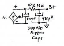
Another idea is to use an extra 100uF 450V cap before the 470uF that is already there, and link them with a 10R 10W. CRC will cut somehow on your PSU ripple, and you will lose just 10V B+. A no space for 2 good chokes situation can benefit somehow from the CRC alternative suggestion. Appreciably better than the single cap you have there now. [/B]
I'm unsure of the layout you mean. You obviously want the caps in parallel but can you draw the circuit with the resistor in so it makes sense to me?
Thanks again...
...another thing I note is that the power cap is running over spec. I'm getting 485Vdc out of it and it's a 450v rated cap.
The transformed supply voltage is claimed to be 295Vac on the schematic but due to the 220/240 difference in supply voltage it's now out of spec. It's actually a little more out of spec than that difference would imply:
220/240=0.917
295/343=0.86 (343 is a guess at the transformed voltage based on 485/1.414.
The heaters were originally 7.38v average, which is
6.3/7.38=0.85
The last two at least correspond with what I'm seeing but it suggests that the thing would be in spec at about 205Vac supply voltage.
Dan
DanDini said:
I'm unsure of the layout you mean. You obviously want the caps in parallel but can you draw the circuit with the resistor in so it makes sense to me?
Thanks again...
In the attached scan you can see what I meant, graphically.
I spec the caps for 500VDC since you have a 'wild' secondary on British mains. Nippon Chemicon caps are obtainable, logically priced, reliable, and will sound better anyway than the soon to dry from over voltage stock one in your amp.
Attachments
Sorry to go a little bit off topic.
Hello, I have a Yaqin MC5881A also.
Wen I turn it on it makes a Hum like yours but in 4 or 5 seconds almost goes to silence (not an absolut silence).
I would like to ask you about the amp's sound, what do you think? Is it ok for you? Can you improve the sound with some other valves?
What valves sould I buy to replace the chinese ones?
Sorry about my english.
Hi Rui, personally I haven't used mine much just to 'listen' as it was obvious from the start that there were some issues that I wanted to deal with before integrating it into my system. I have the same situation as you where the hum is louder initially. It does quieten off, but it is still too loud in my opinion.
If I could resolve this hum I would be happy enough with the sound I think. I have bought some 1980's Russian tubes which are yet to arrive, so I will let you know how they sound.
Thanks for joining in - this could be become the MC-5881 owners' thread if we try hard enough!
Dan
If I could resolve this hum I would be happy enough with the sound I think. I have bought some 1980's Russian tubes which are yet to arrive, so I will let you know how they sound.
Thanks for joining in - this could be become the MC-5881 owners' thread if we try hard enough!
Dan
A Chinese colleague of mine at work has kindly translated the little bits of text on the schematic I posted. There isn't much and you could have guessed it more or less, but it's nice to have...
http://seis.bris.ac.uk/~chdma/files/mc-5881_english.jpg
Dan
http://seis.bris.ac.uk/~chdma/files/mc-5881_english.jpg
Dan
Hello again. My suggestion for output valves would be =C= 6L6Gs. I would be skeptical about substituting the stock Sino 6N1s with just any 6922 because 6N1s are generally smoother. I would discard the blocky gray coupling caps and put Auricaps. I would tweak the PSU to the CRC suggestion I made earlier, discarding the stock cap. I would use Nippon or even better, RIFA. (The initial additional hum, is the sound of the only PSU cap roaring with ripple as it charges). If I could fit it somehow, I would use a choke! CLC instead of CRC. L in the position of the R element in the schematic I posted above. I would trace the GND layout and try to break the ground loops with resistors. Last but not least, I would smack the living daylights out of those luna park 6E2s!
P.S. I attach a picture of the best valves you can use for drivers. Amperex 6DJ8-ECC88. Since 4 of them NOS are going to cost more than the amp itself, just keep em in mind in case you bump on them in some used old circuit or get them for peanuts from some non audiophile ex TV service old man.
P.S. I attach a picture of the best valves you can use for drivers. Amperex 6DJ8-ECC88. Since 4 of them NOS are going to cost more than the amp itself, just keep em in mind in case you bump on them in some used old circuit or get them for peanuts from some non audiophile ex TV service old man.
Attachments
another quick little fix might be to stick a CL-90 on the transformer primary, assuming there isn't some other slow-start device implemented. i'll calm down any current rushing into your heaters, and drop a few volts, which eases the strain on your PT. exceeding the voltage spec on the windings is not a good thing.
The CRC is for sounding better. Nothing to do with the basic ground loop. Keep fiddling with the GND routes. I am optimistic, you will sort it out. You mentioned that one major part of ground noise was that volume and input switch sub PCB loop via chassis and you could not isolate the metal bodies. What about disconnecting the ground side of the coax cables that go to PCB from that sub PCB? Maybe the pot can still see good GND via chassis.
- Home
- Amplifiers
- Tubes / Valves
- Yaqin MC-5881A amplifier improvements