I am slowly gathering the parts to build a copy of the Crystal Palace amplifier, a design by MJ in Valve amplifiers, third edition. Due to copyright reasons I will not post the schematic here, but as lots of people on this forum own the book they know what I am referring to, and will be able to help me out, hopefully. But there are also other designs that are based on the same idea (I have saved a link, but it is out of the air right now, the DCMB idea also illustrates the idea http://www.diyaudio.com/forums/showthread.php?threadid=34536&highlight=
The bias of the output tubes is set by the voltage drop across the anode resistor of the driver (differential pair) tube, making the anodes of the tube negative in relation to the output tubes cathode (thus biasing it). If the driver tube stops to draw current, there will not be voltage drop, and the output tubes lose their bias, and life… MJ included a fuse in line with the B+, which should blow before damage can happen to the tube, but I was thinking about improving the safety of the output tubes a bit much: not that I do not trust MJ, I rather do not trust myself when it comes to amps long term reliability ( I have built some units, but all AC coupled, they still work, but…)
I thought of some possible solutions myself, but am not convinced they will work. A very simple one would be to use the coil of a small HV relay (110VDC, for example) as anode resistor (together with parallel/series resistor, to set ideal load). I have not done the maths, but I think that some mA would be sufficient to activate it. As I plan to use an separate trafo for the output tubes B+, the primary could be wired in series with the NA contact of the relay… but the coils of this relays also have inductance... I do not think this would be a good solution.
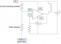
Another solution is current sensing through a small resistor in series with the large plate resistor. The voltage across the resistor could be fed into an opamp, which amplifies it and feeds a relay coil (see the schematic). Problem I see is that it should probably work for DC conditions, but there will also be the superimposed AC, which the opamp will also happily amplify…maybe a cap across the sensing resistor? (lets the AC signal pass, while the DC bias must pass through the resistor… but, something tells me it is not good either.) The idea, again, is to feed the coil of a relay (can be a 6 or 12VDC unit) that will switch the primary of the outputs tube B+ trafo.
Thanks for reading, and I really appreciate any help!
Erik
PS...I have a feeling there is something wrong with the opamp circuit, but I have to eat before I can think lucidly again.
The bias of the output tubes is set by the voltage drop across the anode resistor of the driver (differential pair) tube, making the anodes of the tube negative in relation to the output tubes cathode (thus biasing it). If the driver tube stops to draw current, there will not be voltage drop, and the output tubes lose their bias, and life… MJ included a fuse in line with the B+, which should blow before damage can happen to the tube, but I was thinking about improving the safety of the output tubes a bit much: not that I do not trust MJ, I rather do not trust myself when it comes to amps long term reliability ( I have built some units, but all AC coupled, they still work, but…)
I thought of some possible solutions myself, but am not convinced they will work. A very simple one would be to use the coil of a small HV relay (110VDC, for example) as anode resistor (together with parallel/series resistor, to set ideal load). I have not done the maths, but I think that some mA would be sufficient to activate it. As I plan to use an separate trafo for the output tubes B+, the primary could be wired in series with the NA contact of the relay… but the coils of this relays also have inductance... I do not think this would be a good solution.
Another solution is current sensing through a small resistor in series with the large plate resistor. The voltage across the resistor could be fed into an opamp, which amplifies it and feeds a relay coil (see the schematic). Problem I see is that it should probably work for DC conditions, but there will also be the superimposed AC, which the opamp will also happily amplify…maybe a cap across the sensing resistor? (lets the AC signal pass, while the DC bias must pass through the resistor… but, something tells me it is not good either.) The idea, again, is to feed the coil of a relay (can be a 6 or 12VDC unit) that will switch the primary of the outputs tube B+ trafo.
Thanks for reading, and I really appreciate any help!
Erik
PS...I have a feeling there is something wrong with the opamp circuit, but I have to eat before I can think lucidly again.
Attachments
Hi Wavebourn
Thanks for also jumping in at my questions in this thread.
The cathode follower sure is an option...but in a DC coupled stage, if the driver tube stops conducting the anode resistor will work as a 'grid leak resistor' for the cathode follower stage...that is, there will not be the normal voltage drop across the resistor, and given that the grid of the cathode follower does not draw any current, it will be at the B+ potential, and so will the cathode, still destroying the output tube. Or am I missing something?
Erik
Or am I missing something?
You're not. That's exactly what will happen.
SY said:
You're not. That's exactly what will happen.
But it is very unlikely if cathode follower uses triode from the same tube.
SY said:It doesn't. It may help if you go look the circuit up in MJ's book.
Hmmm... Do you mean that the original schematic in the book already has a cathode follower made of a different tube? I would use the same... If it is out of the socket, or filament blown, both triodes will stop conduct current. Also, emission loss happens approximately together, but it is not so dangerous as removing the tube from the socket or blown filament. I would use something like 12AX7 with 12V filament power.
I have been pointed, through SY, to the fact that it would probably be easier (and safer) to check the current going through the output tubes. If current goes to high, the circuit is killed... An idea would be to use an integrator, and reset it every couple seconds. I understand the idea, I could use a 555 timer to generate the 'signals' needed to reset the circuit, but, if anyone here has something ready and tested, the information would be more than welcome. I just want to keep my output tubes singing for several years!
Erik
Erik
l'esprit d'escalier
Actually, if you run it in Class A, you could even put in a simple threshold detector set at, say, 20% above the nominal idle current. AB makes it slightly more complicated, so either a resettable integrator (sort of like SOA protection in transistor amps) or a clipper similar to the one shown in MJ's autobias circuit should do the trick.
Actually, if you run it in Class A, you could even put in a simple threshold detector set at, say, 20% above the nominal idle current. AB makes it slightly more complicated, so either a resettable integrator (sort of like SOA protection in transistor amps) or a clipper similar to the one shown in MJ's autobias circuit should do the trick.
- Status
- This old topic is closed. If you want to reopen this topic, contact a moderator using the "Report Post" button.
- Home
- Amplifiers
- Tubes / Valves
- current sensing in series with anode resistors