I'm afraid the Hafler and Keroes paper is a piece of "!%*!*?*" that keeps getting quoted endlessly. It's a little overdue that this mess got cleared up.
I just worked out the output Z formula for UL and it essentially gives smooth variation between the triode Zout (or Rp) and pentode Zout as 1/U% ie. (43% UL => U%=0.43 => Zout = Rp_triode/.43)
The effective Mu for the circuit also varies as 1/U% from the triode to the pentode case.
All H & K's chart shows is the effect of a bad mismatch between the tube and output transformer impedance. If the transformer had been properly matched to Zout for each U% on the bottom axis of their chart, one would just get the normal expected performance for a triode with that effective MU and that effective Zout. There is NO optimum U%.
There is nothing special about the 43% or 20% in their charts except for the particular transformer and tube they happened to use for that test. The optimum point on their graph is where it just happens to be matching that tube.
Another serious fault launched by that paper is that one can get away with using the same DC voltage for the screen as for the plate B+. The sharp dropoff in plate current on the left side of all pentode characteristic curves is due to screen capture of plate current when screen voltage is near plate voltage.
Just using a tap off the output primary for the screen causes distortion to set in seriously just around idle conditions. This means the first watt is literally ruined. Hence the bad rap UL got for sound.
The screen should be lowered by at least 50 to 100 volts below the plate to avoid this distortion. A separate winding for the screens is one way to do this, but now-a-days one can just use a resistive divider off the plate driving a low capacitance MOSFET follower for the screen.
Sorry to sink a few sacred ships, but this needed to be corrected.
Don
smoking-amp said:----
Just using a tap off the output primary for the screen causes distortion to set in seriously just around idle conditions. This means the first watt is literally ruined. Hence the bad rap UL got for sound.
---
Don
Ouch...We all know wich Watt is the most important...
Arne K
Just using a tap off the output primary for the screen causes distortion to set in seriously just around idle conditions. This means the first watt is literally ruined. Hence the bad rap UL got for sound.
Don, do you have any distortion measurements to support this? It seems plausible for sure, so I'd think it would be pretty simple to set up and demonstrate or dispose of (depending on experimental results).
Hi Sy,
I haven't done any measurements yet on this, been busy calculating Mu's and Rp's for UL and CFB. Quite illuminating though. I do have the parts handy however to do some measurements. Give me a few days to set up and I will get back with some spectra. (The weather just cleared up here, sunny and warm thru the weekend, so I may be delayed till next week on this!)
I will use the new Fairchild FQP1N50 MOSFETs I discovered recently to buffer the screen voltage from a resistive plate voltage divider. (only 115 pF input C which will drop to 10pF or so effective in follower mode)
I'm thinking that the best test would be in SE mode so the even harmonics will show up too.
Don
smoking-amp said:The screen should be lowered by at least 50 to 100 volts below the plate to avoid this distortion. A separate winding for the screens is one way to do this, but now-a-days one can just use a resistive divider off the plate driving a low capacitance MOSFET follower for the screen.
I wondered if it was as easy as all that, so I found an envelope and scribbled on it.
For PP EL84 (convenient example). We would have 10W into 8ka-a. That means 283VRMS across the primary, or 141VRMS at one end. 141VRMS = 200Vpk and that 200Vpk is sitting on the 300V of the HT, so the anode swings to 500V. If our source follower has its drain connected to the 300V HT and we don't like the way input capacitance rises when Vds drops <30V, then it can only swing to 270V. 270V/500V = 0.54. Or to put it another way, we need a potential divider that effectively gives us a maximum of a 54% tap, setting Vg2 = 162V.
Nothing looks unworkable so far...
Edit: From where do you get your Fairchild MOSFETs?
Hi EC8010,
I think I bought mine from Mouser: FQP1N50 500V
http://www.mouser.com/search/refine.aspx?Ntt=fqp1n50
Reasonably priced too.
There is also a P-channel marvel too:
FQP1P50 500V
At least an order of magnitude improved specs over any other HV
P-channel part I've seen (there's only two others)
Yes, a good idea to keep at least 30 V across them for low capacitance.
I think I have one EL84 around, I mostly have 6HJ5 horizontal outputs which require lowered screen voltages anyway. I'll try and find it for testing SE UL EL84 case. I do have some 6L6GC's around too.
Don
"nice to split the AC and DC conditions of the source follower..."
Yes, exactly what I had in mind.
I've got 100 FQP1N50's on the bench ready to fire up. No problem going MOSFET follower mode here. (and 100 FQP1P50's on the bench for making hybrid Positronic tubes later on!)
Don
Yes, exactly what I had in mind.
I've got 100 FQP1N50's on the bench ready to fire up. No problem going MOSFET follower mode here. (and 100 FQP1P50's on the bench for making hybrid Positronic tubes later on!)
Don
I call that useful.
I've just had another thought. Assuming that experiment confirms smoking-amp's theory, varying the % of the g2 tap should change ra and thereby change the optimum load for maximum power. Looking at it from the opposite direction, you just pick whichever output transformer is handy, work out the % tap required to match your output valve to your load reflected through that transformer and you're away. You can now use any old transformer with any valve...
I've just had another thought. Assuming that experiment confirms smoking-amp's theory, varying the % of the g2 tap should change ra and thereby change the optimum load for maximum power. Looking at it from the opposite direction, you just pick whichever output transformer is handy, work out the % tap required to match your output valve to your load reflected through that transformer and you're away. You can now use any old transformer with any valve...
I'm following with interest the recent posts experimenting with a MOSFET Follower.
Does this approach have significant benefit over the LED or TL431 techniques?
I'm still confused about what sort of voltage drop I should be using on the screen - should it be 50 to 100V below plate as Don says?
John
Does this approach have significant benefit over the LED or TL431 techniques?
I'm still confused about what sort of voltage drop I should be using on the screen - should it be 50 to 100V below plate as Don says?
John
Hi John,
I guess we have gotten a little off your topic here, sorry. For the original triode trick, I think the idea of lowering the screen voltage below the plate is so the screen will absorb less current and dissipate less power. That way the tube can operate with more power overall if its screen dissipation spec was threatened. Maybe some sonic benefits too, don't know. For this trick a fixed voltage drop should be fine and is easy to do.
The MOSFET follower is useful for the case of dropping the screen some % of plate voltage (for Ultra-linear operation), and for this an active follower is needed from some attenuated plate voltage reference. One COULD use a follower to drop a fixed voltage, but it would be overkill.
Hi Wavebourn,
Yes, this is the crux of the matter. Pentode is like open loop gain and triode is like closed loop gain, with lower Mu, lower Zout and lower distortion. This would indicate that full triode, U% = 1, would give the lowest output Z and lowest distortion due to maximum neg. feedback. So H & K's chart would have shown monotonically decreasing distortion as U% increased toward triode (had the transformer impedance been continuously/or equivalently optimised for each Zout).
Hi EC8010,
Yes, I think it provides some new flexibility. It is interesting to look at UL (&CFB too) as a means of changing the Mu and Rp parameters of a triode. One will still be constrained by the max voltage and current limits for the tube, so not all combinations will work out.
And as Wavebourn hinted, lower Mu is equivalent to higher neg. feedback, so this will affect distortion levels. One thing I am curious about is whether distortion will scale as expected with neg. feedback level or whether a given tube will really have some preferred Mu and Z for best results (assuming best or equivalently matched xfmr Z in all cases).
Not sure there is really an optimum xfmr Z either except for power matching. Seems that distortion and power should go down with a higher Z load. And of course, Rp or Zout varies with bias current for any tube too, so I guess we have to specify operation at similar dissipation level to compare apples to apples with any given tube.
My take is that the screen voltage for pentodes provides a means of biasing up current for higher power levels without exceeding plate voltage limitations or drawing g1 current, giving them a practical power advantage over triodes. This seems to still hold in UL mode, even at U%=1 (straight triode) if the screen is rated for a lower voltage than the plate and we can separately bias it up DC wise.
Hi Sy,
Seems likely the distortion would be an even harmonic generator, so this may account for why P-P UL is not painful to listen to. But P-P class AB does convert some even distortion to odd distortion.
Don
SY,
Gee, don't do that to me at the start of a week-end! (Your post #33) The graphs do indicate the tendency though. I have somewhat different ones for the KT88, but there is a difference in mu(g1-g2) for 6L6 and KT88 - I will still post those when ready.
Smoking-amp,
I am wondering what the most elegant way is to state that you are really taking on a large cut by simply dismissing test results in a sort of back-handed way (your post #36). There has indeed been several quite independant tests (including my own) to verify the tendency shown in SY's graphs. In your rather simplified theoretical analysis I suspect that some of your parameters do not stay constant under dynamic conditions. But I did not analyse in depth so you may fault me on that. Still, to find that practical measured results disagree with your conclusions to the extent that it does, does raise the issue that all is not as simple as simple maths - unless you bluntly want to call all tests deception!
I also have a problem that you state that UL ruins "the first watt". If I understood you correctly; you also seem to couple that to the finding that Vg2 must be some 100V lower than Va to eliminate that. What I read there is then that all pentode/triode (connected pentodes) must also ruin the "first watt", unless you maintain that something magical happens as soon as g2 is connected to whatever % of output transformer tap, that suddenly disappears when g2 is either connected to B+ or anode.
As you know the Quad topology does allow working g2 at a lower potential than Va, and I can categorically state that that does little worth mentioning to the distortion figure (other than the difference in electrode voltages would normally be accountable for.) I hope you will understand my difficulty. We do not require test results; we have them: Apart from Hafler and Keroes, from Mullard, GE, Peter Walker (never mind myself); for EL34, EL84, KT66, KT88, 6L6 .......
So .....?")
Gee, don't do that to me at the start of a week-end! (Your post #33) The graphs do indicate the tendency though. I have somewhat different ones for the KT88, but there is a difference in mu(g1-g2) for 6L6 and KT88 - I will still post those when ready.
Smoking-amp,
I am wondering what the most elegant way is to state that you are really taking on a large cut by simply dismissing test results in a sort of back-handed way (your post #36). There has indeed been several quite independant tests (including my own) to verify the tendency shown in SY's graphs. In your rather simplified theoretical analysis I suspect that some of your parameters do not stay constant under dynamic conditions. But I did not analyse in depth so you may fault me on that. Still, to find that practical measured results disagree with your conclusions to the extent that it does, does raise the issue that all is not as simple as simple maths - unless you bluntly want to call all tests deception!
I also have a problem that you state that UL ruins "the first watt". If I understood you correctly; you also seem to couple that to the finding that Vg2 must be some 100V lower than Va to eliminate that. What I read there is then that all pentode/triode (connected pentodes) must also ruin the "first watt", unless you maintain that something magical happens as soon as g2 is connected to whatever % of output transformer tap, that suddenly disappears when g2 is either connected to B+ or anode.
As you know the Quad topology does allow working g2 at a lower potential than Va, and I can categorically state that that does little worth mentioning to the distortion figure (other than the difference in electrode voltages would normally be accountable for.) I hope you will understand my difficulty. We do not require test results; we have them: Apart from Hafler and Keroes, from Mullard, GE, Peter Walker (never mind myself); for EL34, EL84, KT66, KT88, 6L6 .......
So .....?
Hi Johan,
I am not disputing the charts/data that Hafler and Keroes present, but rather their interpretation of them. They present the results as verifying an optimum %UL for minimum distortion. This is true if the transformer is not optimised for Zout versus %UL as their example shows. (ie. they use a fixed primary Z transformer)
My point is that if one recognizes that the tube Rp changes with %UL due to neg. feedback, then the transformer primary Z must be modified versus %UL too, to compare apples with apples. If that is done, then no optimum %UL will show up (other than the expected lower distortion as triode mode is approached due to increased internal neg. feedback). H & K seem to have missed this control on their experiment, leading to wrong conclusions.
Regarding the lower Vg2 (DC), when AC plate current gets captured by the screen grid, it is being put into the primary at say the 43% tap rather than the 100% tap for the plate. This causes a measureable difference in output power and hence distortion.
As the screen is connected closer to the plate % and finally to the plate itself for full triode, this diverted plate to screen current gets put into the primary at a closer tap % to the plate connection, so less and finally no effect is produced. So, yes, the distortion does indeed magically disappear for triode wired configuration.
As Sy pointed out, the distortion from screen current is likely even harmonic and would disappear for near class A operation. Not sure what the biasing was on the Quad.
Don
Smoking-amp and I have posted at similar times; I have only now read his latest contribution (at this time!). Perhaps a few further comments.
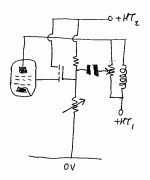
Firstly, I get the idea that we are "mixing up" to a certain extent UL and triode operation. This thread started off with essential triode operation with the main aim of getting more power by lowering the Vg2 (dc) but not decoupling it from the anode ac-wise - fine, where that will be considered usefull. But that is not UL (and I have not reread all posts); from what I saw (on rereading), the operation stayed with g2=anode, ac-wise. The first diagram I saw of an effort to make a g2-tap was that by EC8010 (post #41). Incidentally, EC8010, part of the UL topology is driving the g2 with a low impedance, since there is a g2 internal resistance (similar to ra) which is not high - remember it is essentially triode. So it will be difficult to drive g2 ac-wise as you suggested, from a resistive divider small enough to drive g2 but high enough not to load the output transformer. (This is part of UL output transformer design problems - I mean leakge to the g2 feed etc.)
What must also be remembered is that changing the gm and ra with feedback (i.e. as measured externally), is not necessarily changing it "inside" the tube e.g. in order to get lowest distortion. In a manner of saying, the tube does not know that there is external feedback, and will maintain its specific (internal) performance whether there is feedback or not. Logically NFB will lower whatever distortion is generated inside the tube. But it must be understood that we have here 2 separate factors both to be optomised if one wants to analyse that finely.
Then with regard to output impedance matching, define "matching"! It is common knowledge that for maximum power output the load must equal the internal (generator) impedance. As it happens that is also the condition for maximum distortion. Tube graphs will indicate that usually somewhere just before the output reaches a maximum under specific conditions distortion is a minimum. But when one analyses the distortion, 2nd harmonic has a dip there, while 3rd harmonic keeps on rising, etc. (this for a pentode - triode is different). The scene is rather complex and in that sense there is not a simple optimum. The best is to use manufacturer's graphs or draw one's own and make up one's mind.
Some good news with tubes is that there is mainly lower order distortion, so the solution is likely to lie somewhere where the rate of change of the totaln distortion graph is still lower than the rate of change of the output power (both with regard to load impedance). But again, depending .....
Regards
Busy night!
Your last mail understood, Smoking-amp; few problems there. Perhaps some comments later - it is 04:00 in the AM here, and I want to try to get to bed before the sun comes up. (Off-topic: wickedly hot daytimes here in RSA these days, thus my night owl activities.)
Thanks for interesting debate thusfar!
- Status
- This old topic is closed. If you want to reopen this topic, contact a moderator using the "Report Post" button.
- Home
- Amplifiers
- Tubes / Valves
- Adjustable distributed load discussion