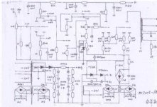
I was able to find this schematic attached with an article on the chinese version of the Meixing amp website. I have an amp with a similar cuircit, though not identical. It looks like, based on comparing that schematic with the insides of my own amp, that the cuircit for the 12ax7 and 12au7 are identical, or close too it. If you guys could look at this schematic and recomend some "tweaks" I might try in order to improve grounding, or other tweaks I might try in order to reduce some of the line noise. Also, certain areas where you feel that parts changes with better parts will make the largest difference in sound. Also, because, especially resistors, some of the parts are very low quality, area's you see as the most important for reliability are good. For instance, those larger sandcast resistors.
Some help on knowing what specific resistor to change in order to reduce the amp's bias. I believe its adjusted through the driver tube, and even getting it at the lowest level the pot allows, it still measures higher than the speced 900 volts, I'm at around 980 volts.
The coupling caps C2 and C6 are bypassed by .022uf caps, I believe, and so I removed those when I upgraded the caps with the .1 and 1uf polystyrene caps from Relcap, as they are self bypassing designs. Was I correct in assuming they are bypassed, and was it a mistake to remove the bypass caps. I have thought about adding back in a cap of similar value to bypass again just to see what happens. On the note I thought you always wanted the bypass cap to be a certain value of the main cap, so that, if you chose .022uf, which is 2.2% of the 1uf, then isn't the .022uf on the .1uf cap 22% of it's value, isn't that too high, or does it really not matter here? Also, C1 is .1uf but was not bypassed with a smaller value.
Again, any feedback on how to improve this cuircit would be appreciated. Unfortunatly, other than this doesn't have the entire power supply cuircit, so I can't show you that. However, unless I missed something, its just a large capaciter bank after the rectifier bridge. It doesn't even appear to have resistors in series to make a CRC supply, so I have considered modifying it that way, as it will easily fit. I would prefer to add some chokes, but a large enough one wont fit. I could use a smaller 250uh choke, but wondered how much value that would be. Also, adding resistors lowers the voltage, but I'm not so sure that is a bad thing, I just need to find out how much before going ahead with it.
An externally hosted image should be here but it was not working when we last tested it.
Oh wow you have drawn up the power supply schematic, I have been looking for that for so long. I was starting to draw it myself, but wanted to make sure I didn't miss anything. I will have to look and see if this looks accurate to my amp. I understand a lot of these amps have different brands and values of parts, even within the same model, sometimes even between channels. My sample didn't have that problem thankfully.
- Status
- This old topic is closed. If you want to reopen this topic, contact a moderator using the "Report Post" button.